A buffering setting method of phase rate matching

A rate matching, staged technology, applied in the direction of error prevention/detection using the return channel, which can solve problems such as retransmission performance degradation, and achieve the effect of improved performance and uniform location distribution

Inactive Publication Date: 2008-07-09
ZTE CORP
View PDF0 Cites 27 Cited by
  • Summary
  • Abstract
  • Description
  • Claims
  • Application Information

AI Technical Summary

Problems solved by technology

[0016] The technical problem to be solved by the present invention is to propose a buffer setting method for one-stage rate matching, which solves the problem that some codewords overlap multiple times while the other part codewords do not overlap during the retransmission process of HARQ packets, which leads to the problem of retransmission performance. falling problem

Method used


Image

  • A buffering setting method of phase rate matching
  • A buffering setting method of phase rate matching
  • A buffering setting method of phase rate matching

Examples


Embodiment 1

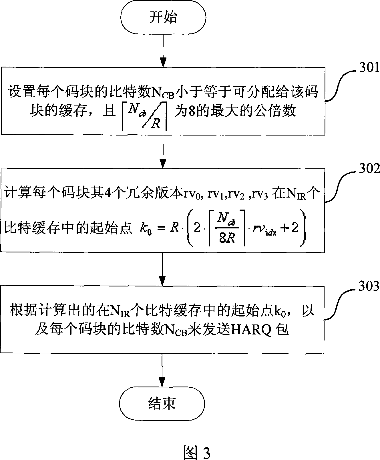
[0046] As shown in FIG. 3 , the first embodiment of the present invention makes the position distribution of RV as uniform as possible by selecting the size of bits of each code block of a suitable HARQ packet, including the following steps:

[0047] Step 301, the sender selects the number of bits N of each code block in the cache cb , set N cb is less than or equal to the buffer that can be allocated to the code block, and is the greatest common multiple of 8; where R is the number of buffer lines specified by the sending end of the digital communication system;

[0048] Among them, you can set or where N IR is the total number of cached bits, C is the number of code blocks, K w is the number of bits after channel coding;

[0049] Step 302, the sender calculates the 4 redundancy versions rv of each code block 0 , rv 1 , rv 2 , rv 3 , at N IR starting point in the bit buffer where rv idx The value is 4 redundant version numbers 0, 1, 2, 3:

[0050] Step 303, ...

Embodiment 2

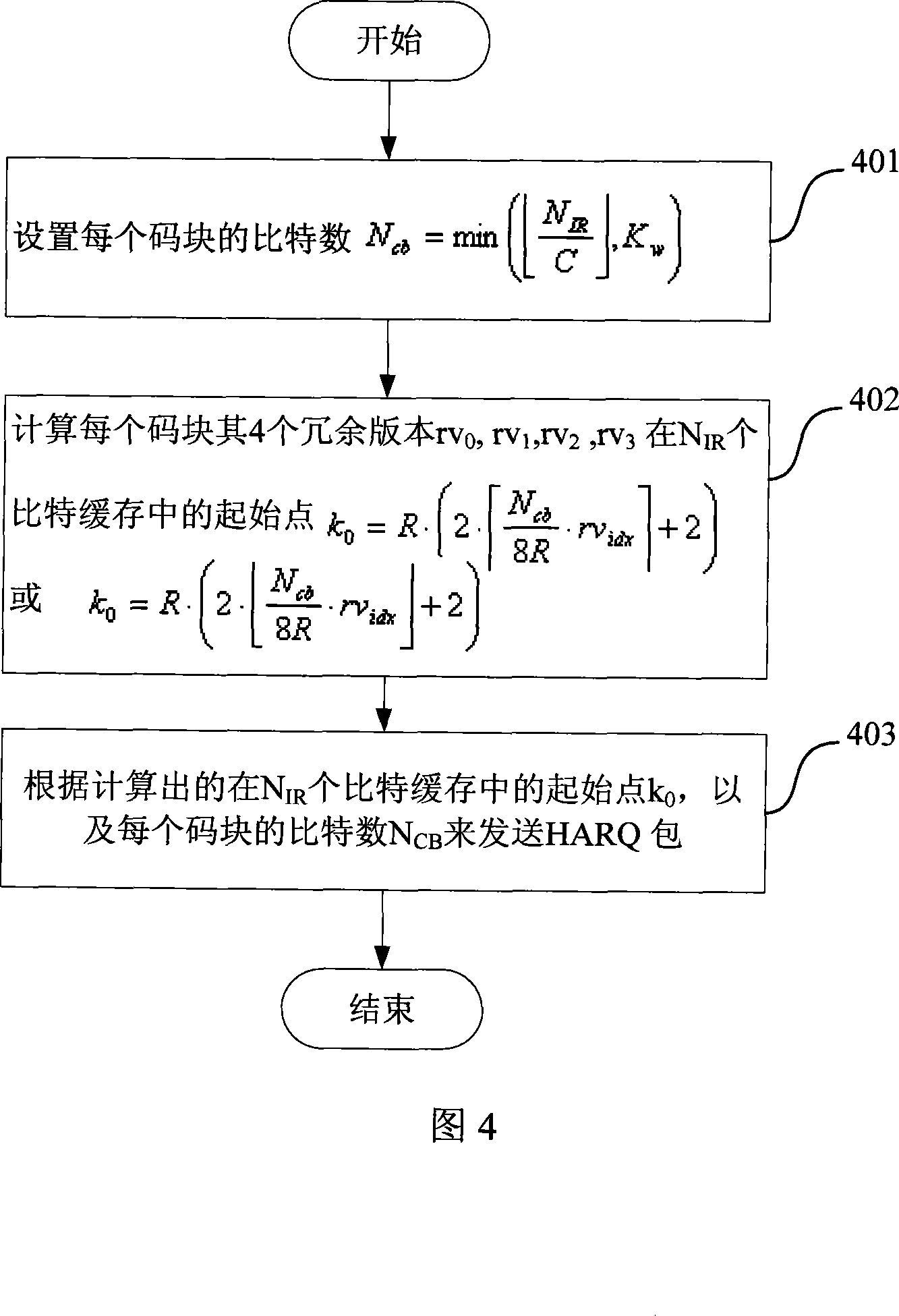
[0054] As shown in FIG. 4, the second embodiment of the present invention makes the position distribution of the RV as uniform as possible by setting a suitable HARQ starting point, including the following steps:

[0055] Step 401, the sender sets the number of bits of each code block in the cache where N IR is the total number of cached bits, C is the number of code blocks, K w is the number of bits after channel coding;

[0056] Step 402, the sender calculates the 4 redundancy versions rv of each code block 0 , rv 1 , rv 2 , rv 3 , at N IR starting point in the bit buffer or, where rv idx The value is 4 redundant version numbers 0, 1, 2, 3, and R is the number of buffer lines specified by the sending end of the digital communication system;


PUM


Abstract

The invention discloses a buffer-setting method matching with a stage speed which is applied to a sending terminal of a digital communication system. The invention comprises the following procedures: the bit number Ncb of each code block is selected in buffering, the Ncb is set to be no larger than the buffering which can be assigned to the code block, the formula (I) is the largest common multiple of 8 and R is the number of rows of the specified area of the sending terminal; the initial point formula (II) of the four redundancy versions rv0, rv1, rv2, rv3 in bit buffering of each code block is calculated, wherein, the value of the rvidx is the number of the four redundancy versions: 0, 1, 2, 3; a hybrid automatic retransmission request packet is sent according to the calculated result of the initial point with the number being NIR in bit buffering and the bit number Ncb of each code block. The invention can lead the positions of RV to be evenly distributed, thus improving the performance of the hybrid automatic retransmission request.

Description

technical field [0001] The invention relates to the field of digital communication, in particular to a buffer setting method for one-stage rate matching of channel coding in a digital communication system. Background technique [0002] The sending end of a digital communication system usually includes the code block to be sent (that is, the source), the channel coder (usually a Turbo channel coder) and the modulator, and the receiving end usually includes a demodulator, a channel decoder (usually a Turbo channel coder) and a modulator. Turbo channel decoder), the code block obtained after decoding (that is, the sink), as shown in Figure 1. Among them, the channel encoder is used to introduce redundant information to the information bits according to certain rules so that the channel decoder at the receiving end can correct the bit errors that occur when the information is transmitted on the channel to a certain extent. [0003] For Turbo codes commonly used in digital commu...

Claims


Application Information

Patent Timeline
Patent Type & Authority Applications(China)
IPC IPC(8): H04L1/18
Inventor 左志松徐俊
Owner ZTE CORP
Why Eureka
Try Eureka