Heat radiator

A technology of heat sink and radiator, applied in cooling/ventilation/heating transformation, electrical components, electrical solid devices, etc., can solve problems such as construction trouble, lack of functionality, inconvenience, etc., to avoid processing, save production costs, and assemble handy effect

Inactive Publication Date: 2008-07-09
Z-COM INC
View PDF0 Cites 3 Cited by
  • Summary
  • Abstract
  • Description
  • Claims
  • Application Information

AI Technical Summary

Problems solved by technology

[0005] 1. At present, the commonly used carrier board is only used to provide substrate support, and the heat sink is directly fixed on the upper surface of the electronic component. However, since the size of the electronic component will change depending on the product itself, the size of the heat sink must also be changed accordingly. , to ensure that it can be correspondingly fixed on the electronic components, which is very inconvenient
And relatively speaking, the bearing plate only has the function of supporting the substrate, and cannot actively support the radiator, and its functionality is insufficient.
[0006] 2. Since the thickness of each electronic component is different, especially there are usually other components on the substrate that can dissipate heat by themselves, such as resistors and capacitors. It is bound to be affected by the resistors and capacitors on the substrate, and cannot actually contact the electronic components. As a result, when the electronic components are in operation, the heat generated cannot pass through the heat transfer of the radiator to achieve the cooling effect; The location of the components, proper processing of the heat sink to match the electronic components, resulting in construction troubles in assembly

Method used


Image

  • Heat radiator
  • Heat radiator
  • Heat radiator

Examples


Embodiment 1

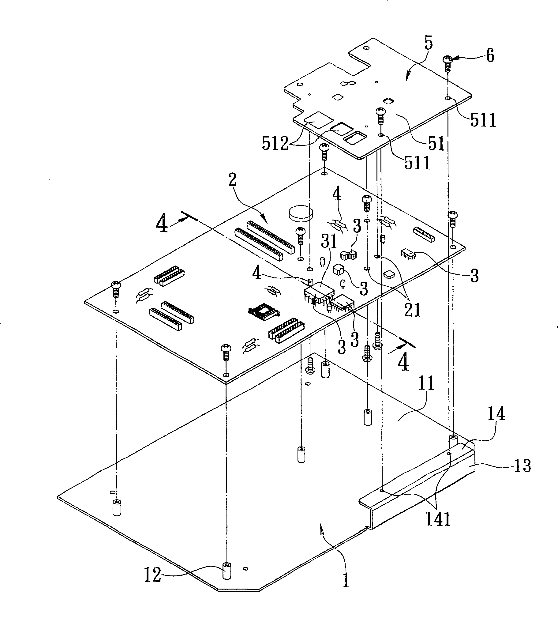
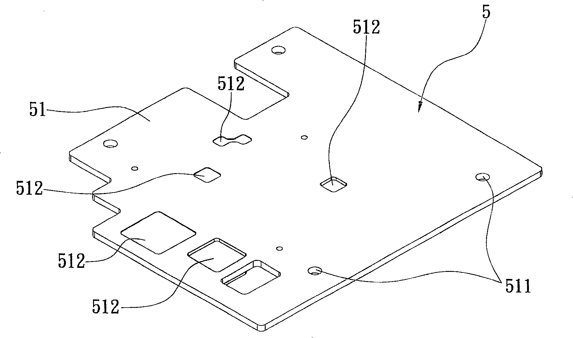
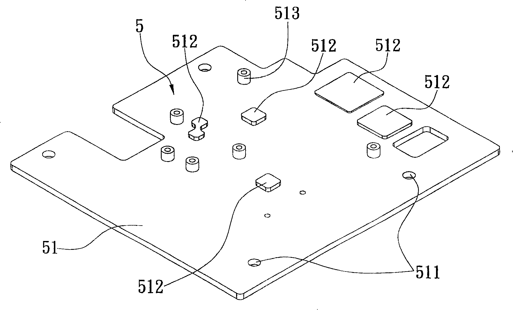
[0038] Such as figure 1 , figure 2 , image 3 , shown in Figure 4 and Figure 5, the present invention includes: a carrier board 1 and a heat sink 5; wherein,

[0039] The carrying plate 1 has a first plate body 11, and the top surface of the first plate body 11 is provided with a plurality of first supporting cylinders 12 upwards, and a second plate body 13 extends upward at least one side end of the first plate body 11, A connecting portion 14 is formed horizontally on the top of the second board 13 , and two first through holes 141 are opened on the surface of the connecting portion 14 of the carrier board 1 .

[0040] A base plate 2, on which a number of electronic components 3 and a number of components 4 such as resistors and capacitors are arranged, and a number of receiving holes 21 are opened on the base plate 2, wherein the above-mentioned first supporting cylinders 12 are just located in this part respectively. Below the part of the container hole 21, a plurality...

Embodiment 2

[0045] As shown in Figure 6, this structure further includes an outer shell 8, and a number of third support columns 15 are provided on the bottom surface of the bearing plate 1 to mount the inner bottom surface 81 of the outer shell 8, and are combined and fixed with the outer shell 8. , so that the loading board 1 is placed on the inner bottom surface 81 of the outer casing 8 , and the second plate body 13 of the loading board 1 is in contact with an inner surface 82 of the outer casing 8 .

[0046] As described above, when the heat generated by the operation of the electronic components 3 passes through the heat conduction plate 51 of the radiator 5 and is transferred to the carrier board 1, it passes through the second plate body 13 of the carrier board 1 and the outer casing 8. The inner surface 82 is in contact to transfer heat to the outer casing 8 and expand heat exchange with the outside air to reduce the operating temperature of the electronic component 3 .

Embodiment 3

[0048] Embodiment 3 of the present invention As shown in FIG. 7 , in this structure, the thermally conductive adhesive 7 is coated between the second plate body 13 of the carrier plate 1 and the inner surface 82 of the outer casing 8 .

[0049]With the above structure, the heat transfer efficiency is increased by the thermally conductive adhesive 7 coated between the second plate body 13 and the inner surface 82 of the outer casing 8 .


PUM


Abstract

The invention provides a heat dissipation device used for arranging a baseplate. The baseplate is provided with a plurality of electronic components; the heat dissipation device comprises a bearing plate which is provided with a first plate body on which the baseplate is fixedly arranged; a second plate body extends upwards by at least one side end of the first plate body; furthermore, the top of the second plate body forms a combination part; the invention also provides a radiator which is provided with a heat conductive plate which is made of metal material and arranged above the baseplate correspondingly; furthermore, one edge of the heat conductive plate is fixedly connected with the combination part of the bearing plate; the bottom surface of the heat conductive plate is respectively contacted with the surfaces of all the electronic components on the baseplate correspondingly; the heat energy which is emitted when the electronic components work is absorbed by the heat conductive plate of the radiator and the heat energy is then transferred to the bearing plate through the combination part and exhausted through the surfaces of the first plate body and the second plate body of the bearing plate. The radiator of the invention can achieve the beneficial effects of convenient assembly, avoiding processing and saving manufacturing cost.

Description

technical field [0001] The invention relates to a heat dissipation device, in particular to a heat dissipation system for laying out electronic components. Background technique [0002] The operation of electronic components inside all electronic products will generate heat. If the heat is not discharged, the electronic components will be damaged due to overheating. In particular, integrated circuits (integrated circuits) use microelectronics technology to shrink electronic components into a single chip, which is characterized by small size, multiple functions, and easy use. However, relatively, the heat generated during its operation is also relatively high, and at the same time it cannot be discharged naturally by simply relying on air convection. [0003] At present, the way of fixing and dissipating heat for electronic components in the industry is to fix the substrate with a number of electronic components on the upper end on a carrier plate, and arrange a heat sink ab...

Claims


Application Information

Patent Timeline
Patent Type & Authority Applications(China)
IPC IPC(8): H05K7/20H01L23/36
Inventor 陈俊逸
Owner Z-COM INC
Why Eureka
Try Eureka