
Crane with heavy frame beam

A crane, heavy-duty technology, applied in the direction of cranes, erection/assembly of bridges, bridges, etc., to achieve the effect of improving construction quality and progress, simple structure, and convenient construction

Active Publication Date: 2010-06-02
CHINA RAILWAY MAJOR BRIDGE ENG GRP CO LTD
View PDF8 Cites 0 Cited by
  • Summary
  • Abstract
  • Description
  • Claims
  • Application Information

AI Technical Summary

Problems solved by technology

There are no literature reports on cranes with this structure

Method used


Image

  • Crane with heavy frame beam
  • Crane with heavy frame beam
  • Crane with heavy frame beam

Examples


Embodiment Construction

[0015] The present invention will be further described below in conjunction with accompanying drawing:

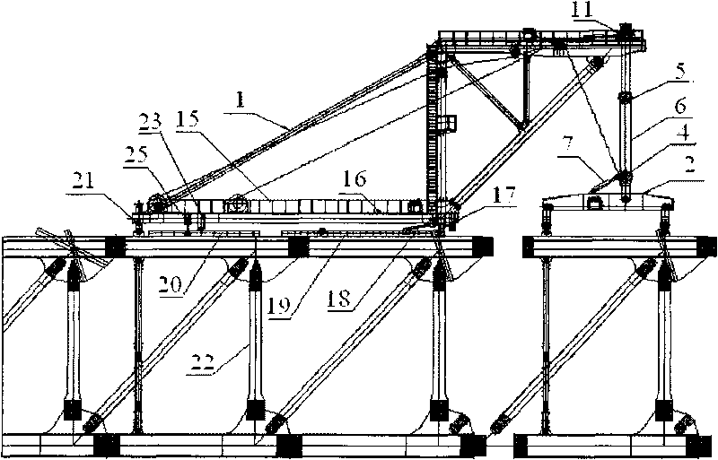
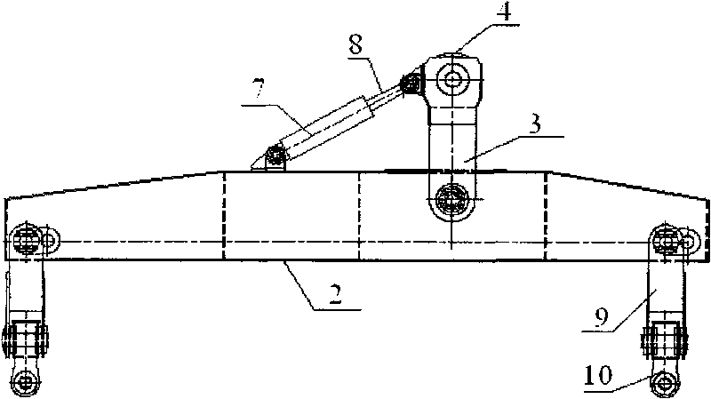
[0016] like figure 1 , image 3 As shown, the present invention is made up of frame 1, crane, whole machine forward-moving mechanism, lifting point translation mechanism and anchoring device, and the spreader girder 2 of crane is hinged with pull plate 3, and pulley 4 is housed on pull plate 3, The pulley 4 is connected with the moving pulley block 5 of the crane through the steel cable 6, the main beam 2 of the spreader is equipped with a leveling oil cylinder 7, and the piston rod 8 of the leveling oil cylinder 7 is obliquely fixed on the pull plate 3. The relative angle between the main beam of the spreader and the moving pulley block 5 is changed by the expansion and contraction of the piston rod 8 of the leveling oil cylinder 7 to achieve the purpose of slope adjustment. like Figure 4 As shown, the two ends of the main beam 2 of the spreader are connected with a po...


PUM


Abstract

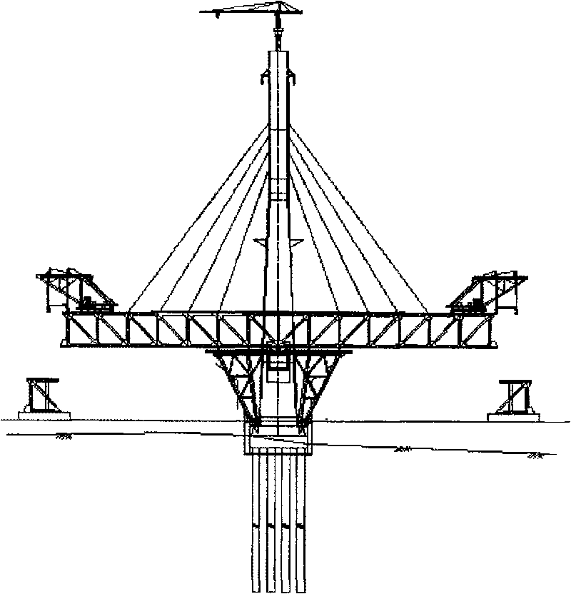
The invention relates to a lifting device, in particular to a crane with a heavy girder erection used for the construction of a steel truss girder in a bridge project. The invention comprises a frame,a lifting machine, an entire machine forward moving mechanism, a lifting point horizontally moving mechanism and an anchoring device, characterized in that a lifting main girder of the lifting machine is articulated with a pulling board; the pulling board is provided with a block which is connected with a traveling block group of the lifting machine through a steel rope; the lifting main girder is provided with a leveling cylinder; a piston rod of the leveling cylinder is inclined and fixed on the pulling board. The invention has the advantages of simple structure and convenient construction;the invention can adjust the angle of the lifting main girder to reach the target of gradient adjustment, allow the lifting point to vertically and horizontally move conveniently, and thus safely andaccurately lifting a steel girder section to a bridge surface; contraposition and splicing can be carried out through the combination between a vertical and horizontal moving mechanism of the liftingpoint and a leveling mechanism of the lifting machine, so as to improve the construction quality and progress of the bridge.

Description

technical field [0001] The invention relates to a hoisting device, in particular to a heavy-duty girder erecting crane used in the hoisting construction of steel truss girders in bridge engineering. Background technique [0002] In China, the erection of steel truss girders is generally carried out in bulk, and the lifting capacity of the girder crane is designed according to the weight of the largest member of the steel truss girder. For example, the maximum member weight of the steel truss girder of the Wuhu Yangtze River Bridge is 50t. When the crane is designed, the lifting capacity is only 50t. In the case of multiple main trusses, the deformations of the side trusses and the middle trusses of the erected sections are inconsistent, and the deformations of the side trusses and the middle trusses of the hoisted steel truss girders are also inconsistent. In the case of multiple trusses, the lifting capacity of the crane and the deformation coordination with the erected se...

Claims


Application Information

Patent Timeline
Patent Type & Authority Patents(China)
IPC IPC(8): B66C13/08B66C23/18B66C1/10E01D21/00B66C9/14
Inventor 秦顺全胡汉舟姚发海杜斌武朱林达高培成孟莎马涛
Owner CHINA RAILWAY MAJOR BRIDGE ENG GRP CO LTD
Learn More