Charged particles ray irradiation device

A technology of charged particle beams and irradiation devices, applied in X-ray/γ-ray/particle irradiation therapy, circuits, discharge tubes, etc.

Active Publication Date: 2008-07-23
PRESIDENT OF NAT CANCER CENT +1
View PDF1 Cites 13 Cited by
  • Summary
  • Abstract
  • Description
  • Claims
  • Application Information

AI Technical Summary

Problems solved by technology

However, in this technology, since the PET camera is fixed and can only confirm the position of a specific part, it is necessary to check the position of the desired part

Method used


Image

  • Charged particles ray irradiation device
  • Charged particles ray irradiation device
  • Charged particles ray irradiation device

Examples


Embodiment Construction

[0022] Hereinafter, a preferred first embodiment of the charged particle beam irradiation apparatus of the present invention will be described with reference to FIGS. 1 to 5 . In addition, in description of drawings, the same code|symbol is attached|subjected to the same or equivalent element, and repeated description is abbreviate|omitted. In this embodiment, a case where a charged particle beam irradiation device is used as a proton beam therapy device will be described.

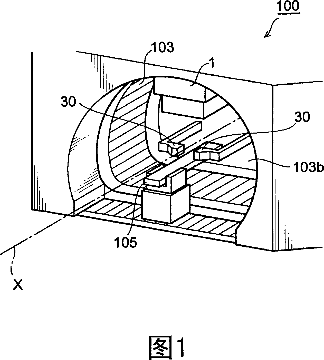
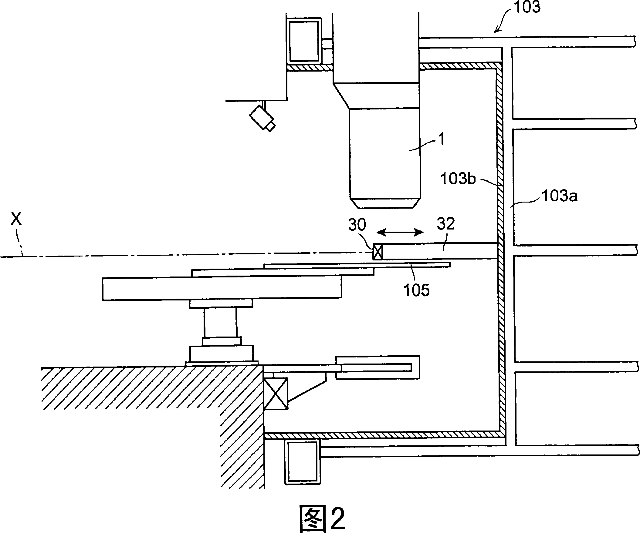
[0023] As shown in FIGS. 1 to 3 , a proton beam therapy apparatus 100 is an apparatus for irradiating a proton beam (charged particle beam) to a tumor (irradiation target) P inside a patient (irradiated subject) 51 .

[0024] This proton beam therapy apparatus 100 has a proton beam irradiation unit (charged particle beam irradiation unit) 1 mounted on a rotating gantry 103 (irradiation chamber) and rotatable around a treatment table (placement table) 105 .

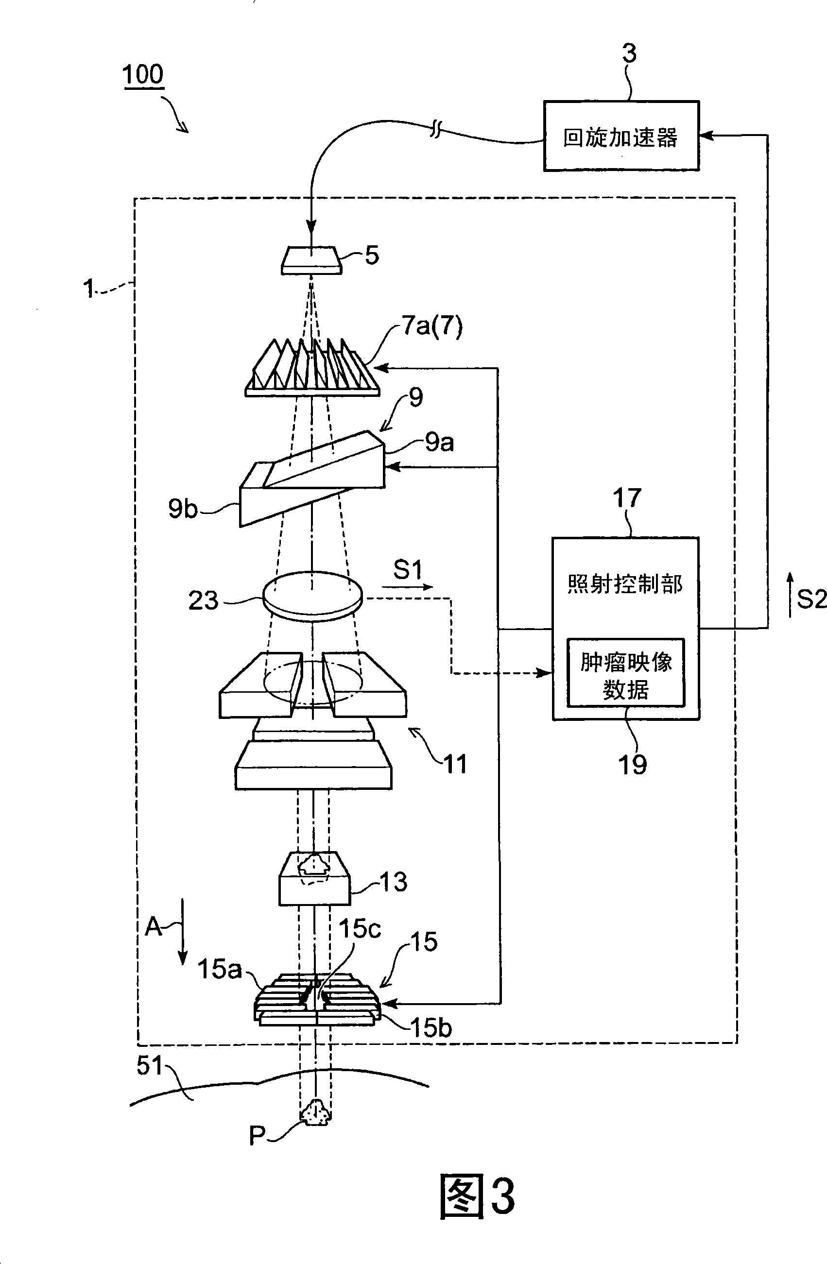
[0025] As shown in FIG. 3 , the proton beam irr...


PUM


Abstract

The invention provides a charged particle ray irradiation unit for confirming the irradiation position of desired site. An irradiation room (103) comprises a charged particle ray irradiation part (1) rotating around the irradiated object (51), a detection part (30) for detecting the silent gamma ray generated by the irradiated object (51) which can move along the extending direction of the pivot point X of the charged particle ray irradiation part (1). Thus, the detection part moves along the direction of the X axle to prevent the detection part (30) interfering the rotation of the charged particle ray irradiation part (1). Moreover, when the irradiated object moves into and out the irradiation room (103), the detection part (30) is out of the way. And, the position confirmation of the desired site can be performed. The detection part (30) moves upwards along the direction of axle X and cooperates with the size of the irradiation object, thus the detection range of the detection part (30) can be enlarged.

Description

technical field [0001] The present invention relates to a charged particle beam irradiation apparatus provided with an irradiation chamber having a charged particle beam irradiation unit rotatable around an irradiation target to which charged particle beams are irradiated. Background technique [0002] Conventionally, as a charged particle beam irradiation device that irradiates charged particle beams, for example, a proton beam therapy device that treats tumors by irradiating proton beams is known. In such tumor treatment, it is necessary to design an irradiation plan such as absolute dose, dose distribution, and irradiation position according to the shape and position of the tumor, and to perform irradiation of charged particle beams with high precision according to the irradiation plan. When irradiating a patient with proton beams, the accuracy of the irradiation position is particularly important in order to avoid irradiation of vital organs, brainstem, optic nerve, spin...

Claims


Application Information

Patent Timeline
Patent Type & Authority Applications(China)
IPC IPC(8): A61N5/01A61N5/10
CPCA61N5/1043A61N5/1079G03F1/20G03F5/02G03F7/70208G03F7/70275G03F7/7085H01J37/28
Inventor 西尾祯治荻野尚野村和弘立川敏树
Owner PRESIDENT OF NAT CANCER CENT
Why Eureka
Try Eureka