Electric point gum machine and working way thereof

A technology of dispensing device and working method, which is applied to the device and coating of surface coating liquid, which can solve the problems of unstable working pressure of compressed air, fluctuation of fluid injection speed, difficulty in increasing injection speed, etc., and achieve mobile The effect of constant speed, increased injection speed, and stable rotational speed

Inactive Publication Date: 2008-07-23
PRECISION TECH DEV SHENZHEN
View PDF0 Cites 30 Cited by
  • Summary
  • Abstract
  • Description
  • Claims
  • Application Information

AI Technical Summary

Problems solved by technology

[0007] 2. Due to the instability of the working pressure of compressed air and the change of fluid viscosity, the speed of fluid injection is also fluctuating
[0008] As a result of the above deficiencies, traditional dispensing devices have relatively low injection accuracy and limited injection speed
If it is a high-viscosity fluid, it is more difficult to control the injection accuracy and increase the injection speed

Method used


Image

  • Electric point gum machine and working way thereof
  • Electric point gum machine and working way thereof
  • Electric point gum machine and working way thereof

Examples


Embodiment 1

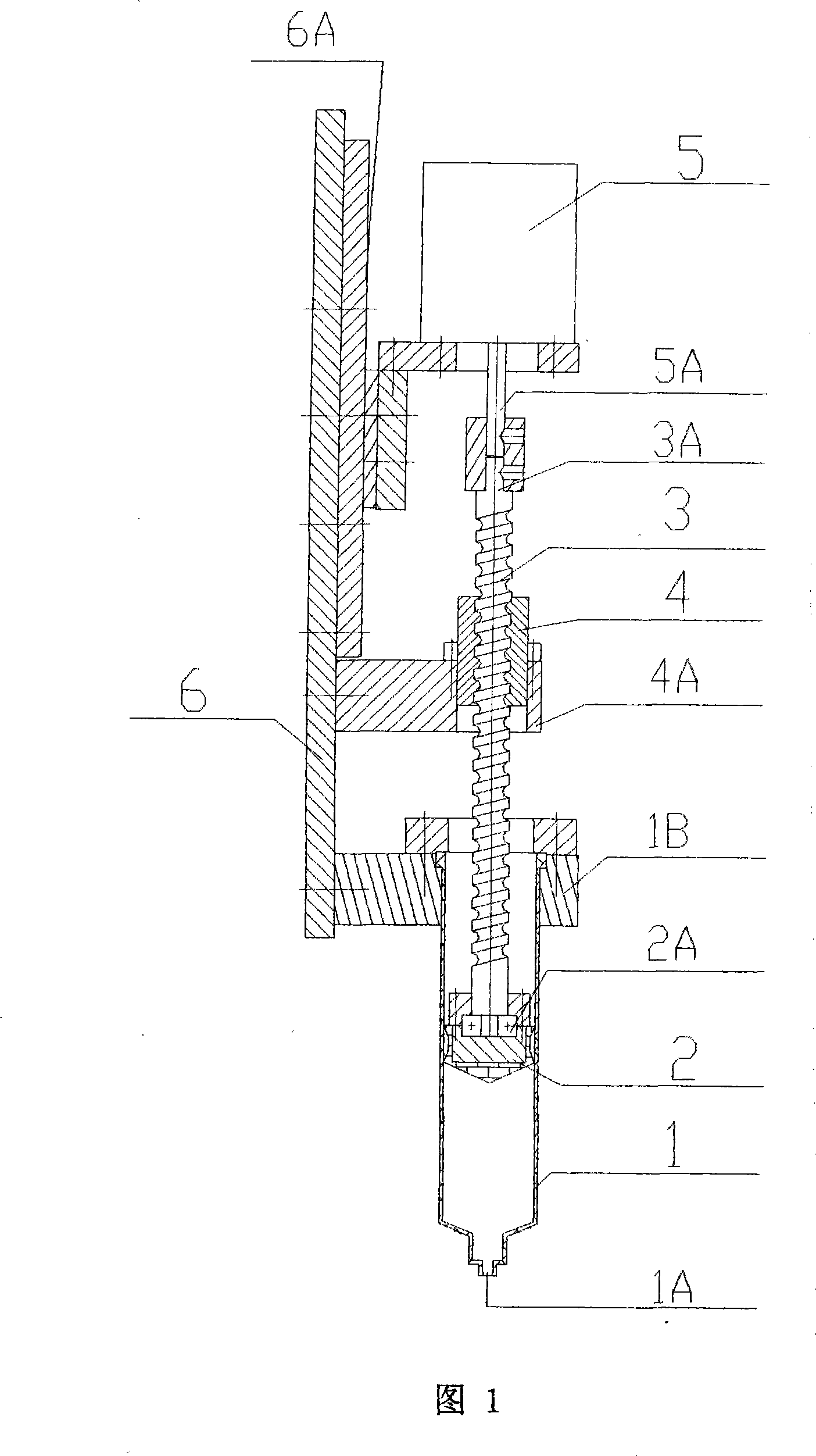
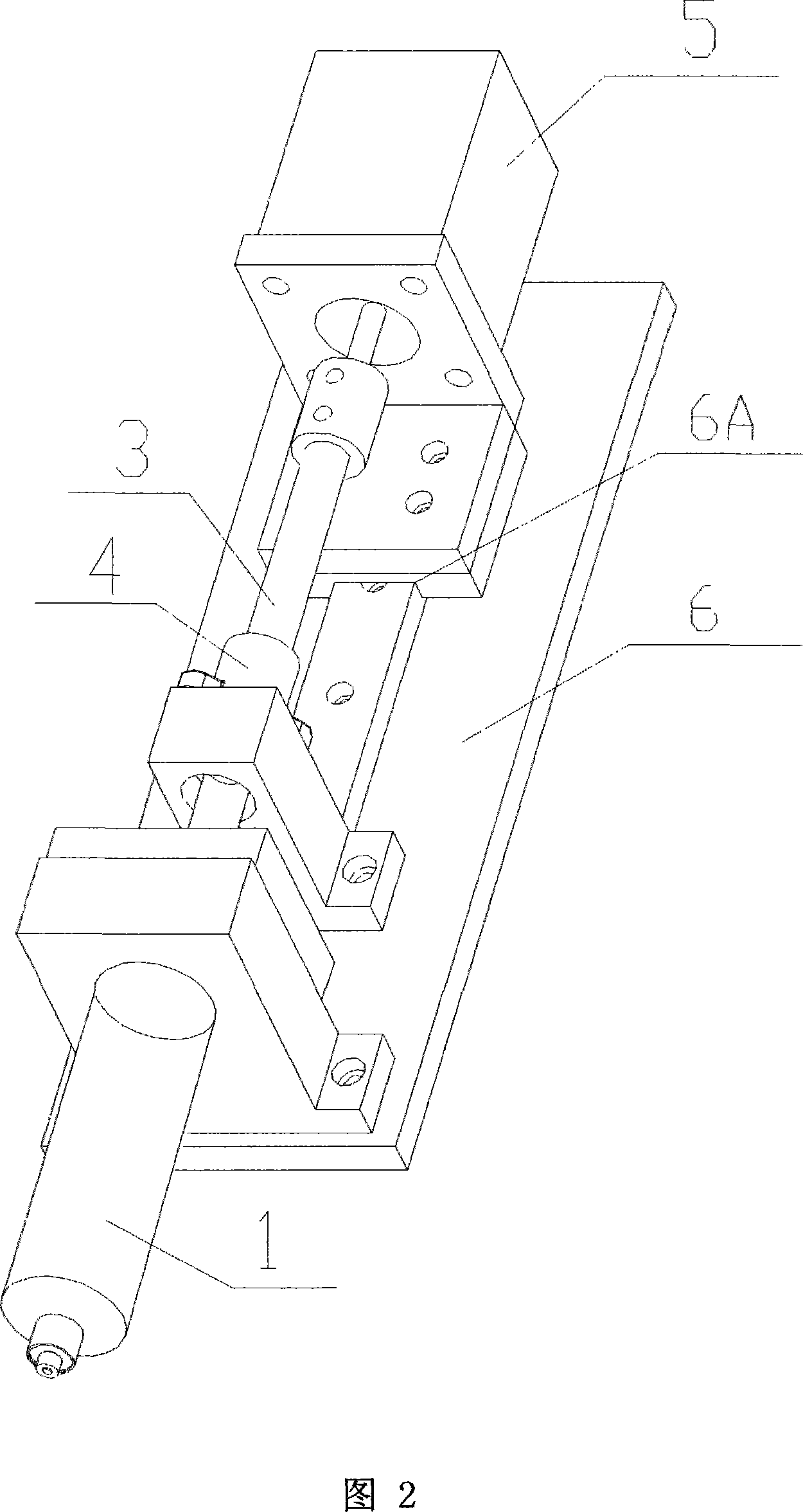
[0030] Figure 1 and Figure 2 are a front view and a perspective view of Embodiment 1 of an electric dispensing device, respectively.

[0031] It can be seen from the above figure that the injection barrel 1 for storing liquid has a discharge port 1A in the center of the bottom end of the barrel, and the barrel 1 is fixed on the lower part of the connection base 6 through the mounting plate 1B. The injection barrel 1 is provided with a pusher piston 2, and the piston 2 can slide up and down in the barrel 1 to squeeze the liquid in the barrel 1 or suck the liquid outside the barrel 1. A bearing 2A is installed inside the pushing piston 2, and the piston 2 is connected to the lower end of the transmission screw 3 through the bearing 2A, and the screw 3 can rotate relative to the piston 2. The fixed nut 4 used in conjunction with the screw rod 3 is installed on the middle and lower part of the base 6 through the connecting plate 4A, the position of the nut 4 relative to the barrel...

Embodiment 2

[0047] Fig. 5 is a front view of Embodiment 2 of the electric dispensing device.

[0048]As can be seen from the figure, its main difference with Embodiment 1 is: the structure of the pushing piston 2 is different, and it has been changed into a plunger type. The connection between the piston 2 and the transmission screw rod 3 is also different. The top of the piston 2 has an external thread and is screwed into the bottom of the bearing seat 2B. The piston 2 is connected to the lower end of the screw rod 3 by the bearing 2A in the bearing seat 2B.

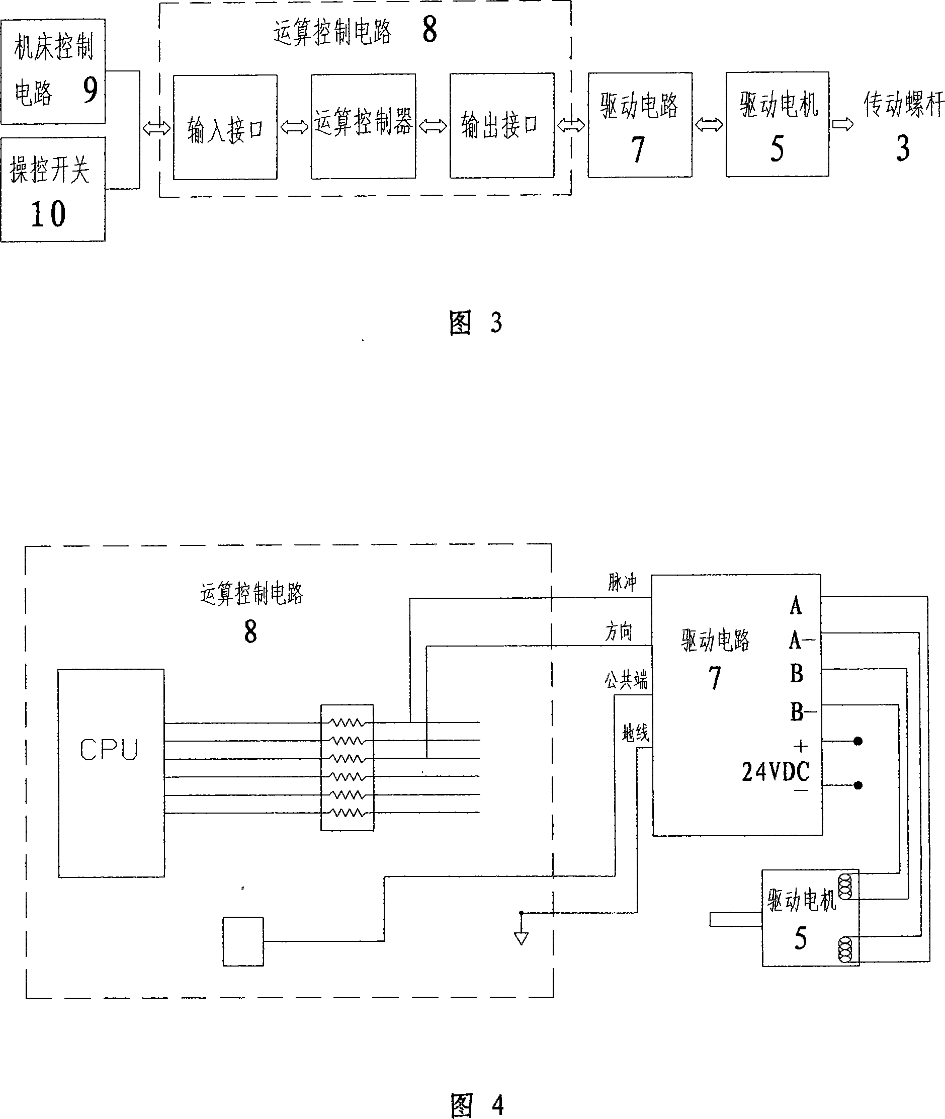
[0049] The electric dispensing device of the present invention can be realized by manipulating the switch 10,

[0050] 1. Burst:

[0051] Press the button to start the injection, and the injection will not end until the button is released.

[0052] Press the button to start the injection, and the injection will not end until the preset cycle time.

[0053] 2. Continuous shooting:

[0054] Injection starts when a start signal is...


PUM


Abstract

The invention discloses a motor adhesive injecting device and an operating mode thereof. The device comprises a shooting cylinder which is provided with an outlet at the bottom, a pressure ram arranged inside the shooting cylinder, a drive screw connected with the upper part of the pressure ram, a fixing screw used together with the drive screw and a drive motor arranged on top of the drive screw. The rotation of a motor drives the screw to make the spiral movement inside the nut and drives a piston to have the axial displacement to act on the liquid. The operating mode is that the rotating axle of the motor is controlled to continuously rotate, discontinuously rotate, impulse rotate or reverse the axle to drive the piston to move up and down or vibrate correspondingly to the cylinder. With excellent response, the motor can control the injection rate accurately by the controlling the rotating angle. The motor can satisfy the requirements for accurate and rapid adhesive injecting for the constant running speed and uniform flowing speed of the liquid.

Description

technical field [0001] The invention relates to the technical field of glue dispensing equipment, in particular to the structural improvement and the design of the working mode of the glue dispensing device, which can be widely applied to various types of industrial production, such as manufacturing printed circuit boards and other industries. Background technique [0002] In industries such as electronic product manufacturing, clothing industry, and watchmaking industry, dispensing devices are often required to inject some colloidal fluid into the work surface, or into some relatively small gaps, or for decorative purposes, to add color The fluid is injected into the workpiece to form some patterns. [0003] The traditional glue dispensing device has an injection barrel for loading fluid, and a discharge port is arranged at the lower end of the barrel. Compressed air enters the upper part of the barrel through the control valve, pushes the fluid in the barrel, passes throu...

Claims


Application Information

Patent Timeline
Patent Type & Authority Applications(China)
IPC IPC(8): B05C5/02B05C11/10B05D1/26B05D7/24
Inventor 曾运添
Owner PRECISION TECH DEV SHENZHEN
Why Eureka
Try Eureka