Supercharge Your Innovation With Domain-Expert AI Agents!

Method for controlling a moveable tool, apparatus and mechanical tool

A technology for moving tools and mechanical tools, applied in manufacturing tools, general control systems, metal processing equipment, etc.

Inactive Publication Date: 2013-07-10
FRITZ STUDER AG GLOCKENTHAL
View PDF6 Cites 0 Cited by
  • Summary
  • Abstract
  • Description
  • Claims
  • Application Information

AI Technical Summary

Problems solved by technology

[0003] Furthermore, since errors may be prone to occur when entering the values, and precise determination of the respective values ​​requires the operator to have a certain level of experience to obtain the desired accuracy in the machined workpiece degree, so the specification of the feed function deteriorates

Method used


Image

  • Method for controlling a moveable tool, apparatus and mechanical tool
  • Method for controlling a moveable tool, apparatus and mechanical tool
  • Method for controlling a moveable tool, apparatus and mechanical tool

Examples


Embodiment Construction

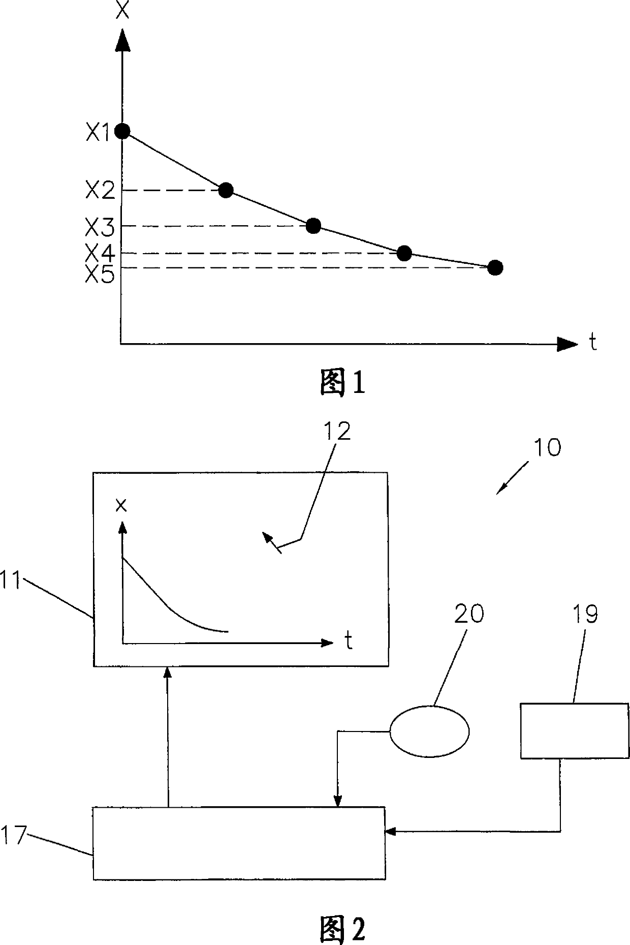
[0020] Figure 1 shows a graph of a known type of feed function. The abscissa t corresponds to the time axis, and the ordinate x specifies the position of the tool on the x-axis.

[0021] In order to determine the feed function, for the positions X1, X2, X3, X4, X5 of the tool and between the positions of the tool, i.e. between X1 and X2, between X2 and X3, between X3 and X4 and between X4 and X5 Each travel speed V1, V2, V3, V4 of the inter-movement specifies a value respectively. If the tool is e.g. a grinding wheel, X1 corresponds to the contact position, e.g. where the tool hits the workpiece surface, X2 corresponds to the first transition position from which material is removed by roughing, X3 corresponds to the second transition position, where material is removed from this second transfer position by semi-finishing, X4 corresponds to a third transfer position from which fine-finishing begins, and X5 corresponds to the final position of the tool to obtain finished dimens...


PUM


Abstract

The method involves stimulating temporary movement of a tool in an axle by an adjusting function. An output adjusting function is represented in the form of an output adjusting curve (29) on a monitor. An adjusting function is computed from the output adjusting function and inputs that are input by a pointing device e.g. computer mouse and touch screen. The adjusting function is represented as an changed output adjusting curve, and control commands for operating the tool is produced from the adjusting function. Independent claims are also included for the following: (1) a processing machine comprising a tailstock (2) a computer program having a set of instructions to perform a method for controlling an operatable tool (3) a data carrier having a set of instructions to perform a method for controlling an operatable tool.

Description

technical field [0001] The invention relates to a method and a device for controlling a movable tool, an input device for implementing the method and a machine tool with the input device. Background technique [0002] Machine tools are known which allow precision machining of workpieces by moving the tool in a controlled manner. The position of the tool over time is defined here by a feed function specified according to the desired workpiece geometry. However, only relatively simple feed functions can be specified. For example, in the case of a grinding machine, by turning a potentiometer, the operator is able to define values ​​for different positions of the grinding wheel, such as the contact position where the grinding wheel hits the workpiece, and for a specific travel speed of the grinding wheel between the two positions , the transition position where material is removed by semi-finishing and the final position where the grinding wheel obtains the finished size. ...

Claims


Application Information

Patent Timeline
Patent Type & Authority Patents(China)
IPC IPC(8): B24B51/00G05B19/404G05B19/4069
CPCG05B2219/36171G05B2219/45161G05B19/409
Inventor 阿尔弗雷德·格高夫马丁·阿比尔
Owner FRITZ STUDER AG GLOCKENTHAL
Features
  • R&D
  • Intellectual Property
  • Life Sciences
  • Materials
  • Tech Scout
  • Unparalleled Data Quality
  • Higher Quality Content
  • 60% Fewer Hallucinations
Learn More