Craft knife capable of automatically locking blade position

A utility knife and blade technology, applied in the field of utility knives, can solve the problems of short product life, frequent ratchet movement relative to the knife shell, and failure of the locking mechanism, etc., to achieve easy manufacturing, long service life, and simple structure Effect

Inactive Publication Date: 2008-07-23
周晓刚
View PDF1 Cites 7 Cited by
  • Summary
  • Abstract
  • Description
  • Claims
  • Application Information

AI Technical Summary

Problems solved by technology

[0003] But in this design scheme, the I-shaped guide rail in the push button is to rely on the elastic stopper on the knife seat to limit its position relative to the locking mechanism and make it abut against one side of the brake block in the locking mechanism. Therefore, In this design scheme, the size, position and mutual force cooperation of the elastic stopper on the tool seat, the I-shaped guide rail in the push button and the brake block in the locking mechanism need to be very precise, with slight deviations. It will make the protrusion in the locking mechanism break away from the ratchet teeth of the knife case, that is, make the locking position of the blade relative to the knife case invalid. This increases the difficulty of the actual production of the utility knife. During the process, the elastic stopper is easy to lose its elasticity, which will cause the automatic locking of the blade to fail, making the utility knife unable to work normally; at the same time, in this design scheme, the locking mechanism needs to move frequently relative to the knife seat, and its setting on the knife seat It is more difficult, and the elastic stopper also needs to move relative to the tool seat, and its setting on the tool seat is also difficult to realize. These are not conducive to actual production and implementation, and how to set it is not mentioned in this patent document; moreover, The protrusions in the locking mechanism need to frequently move relative to the ratchet teeth of the knife case, and ordinary utility knives are generally made of engineering plastics except for the blade. When the utility knife is used after the blade has been automatically locked, the force acting on the blade It will be between the protrusion and the ratchet of the knife case, which will easily cause the protrusion to break, and then lead to the failure of the locking mechanism, and the service life of the product is not long

Method used


Image

  • Craft knife capable of automatically locking blade position
  • Craft knife capable of automatically locking blade position
  • Craft knife capable of automatically locking blade position

Examples


Embodiment Construction

[0019] The present invention will be further described in detail below in conjunction with the accompanying drawings and embodiments.

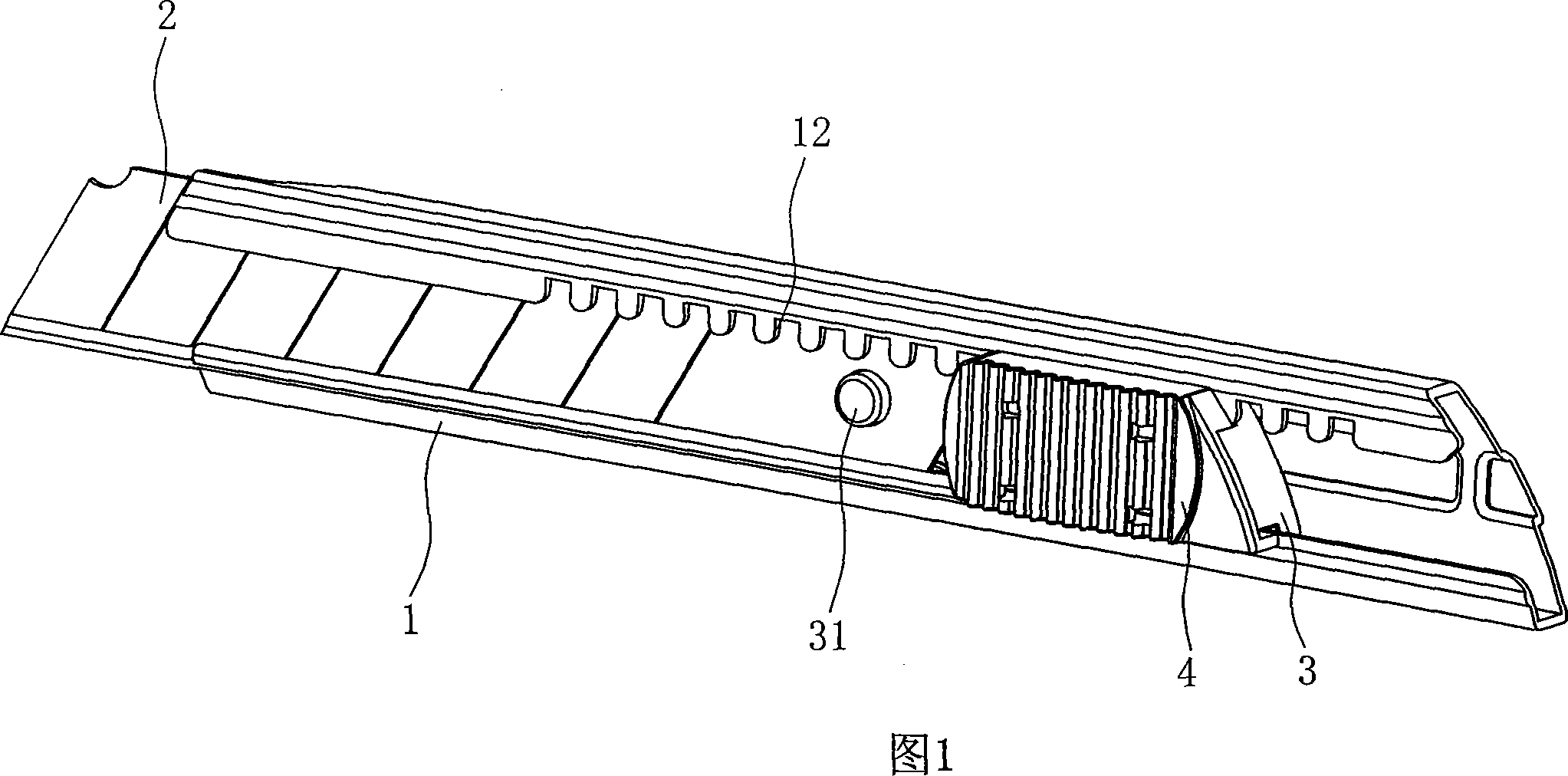
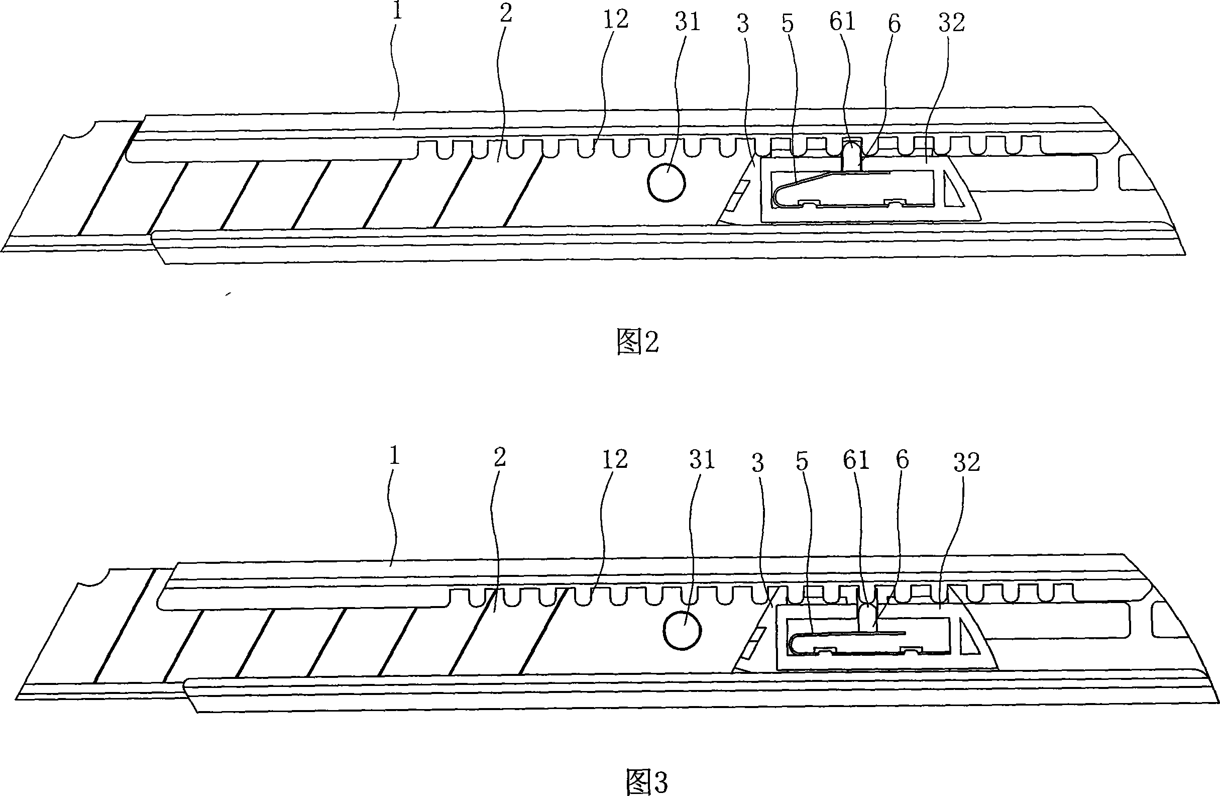
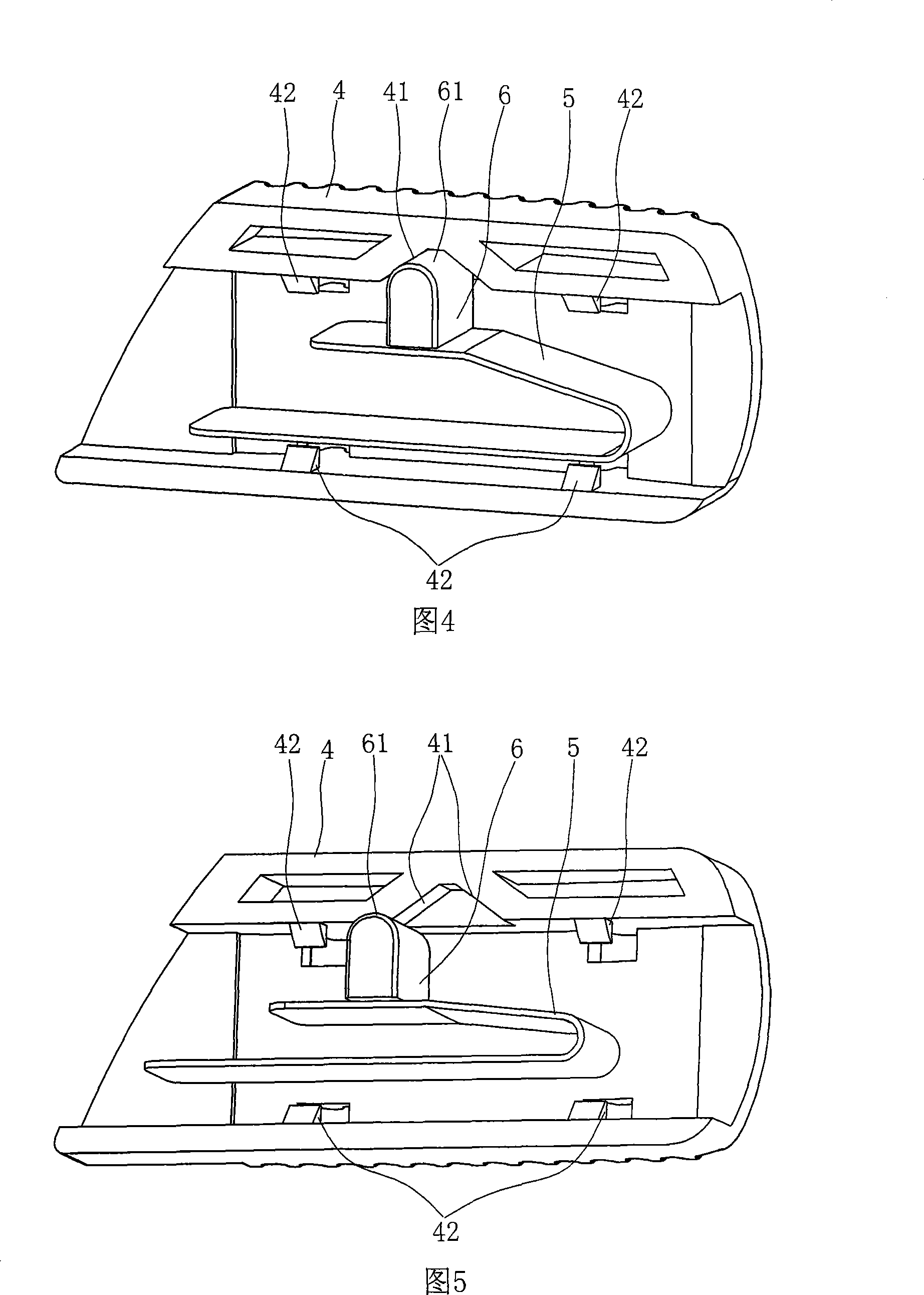
[0020] As shown in Figures 1 to 6, the utility knife with automatic blade locking includes a knife case 1 with a chute 11, and a blade 2 that is inserted in the chute 11 of the knife case 1 and can move back and forth relative to the knife case 1. With the knife seat 3 and the push cover 4 which is arranged on the surface of the knife seat 3 and can push the knife seat 3 to move;

[0021] Wherein, the inner edge of the cutter housing 1 on one side of the chute 11 is provided with a continuous protruding tooth 12, and the head of the protruding tooth 12 is smoothly transitioned;

[0022] The knife seat 3 is arranged on the rear portion of the blade 2, and the front portion of the knife seat 3 is provided with a boss 31, and the boss 31 is inserted into the socket 21 on the blade 2 to block the blade 2, thereby The knife seat 3 together with th...


PUM


Abstract

The invention relates to a craftsman knife, which can automatically lock a blade and includes a knife case (1), a blade (2), a knife file (3) and a push cover (4), wherein, a continuous double wedge (12) is arranged on the knife case (1), the knife file (3) is arranged behind the blade (2), an elastic element and a locking piece (6) the head (61) of which is rounded off, are arranged in the knife file (3), the elastic element has the tendency to push the head (61) of the locking piece (6) into a space between the double wedge (12) on the knife case (1), an inclined plane (41) is arranged at the back of the push cover (4) at each side of the head (61) of the corresponding locking piece (6), the two inclined planes (41) are opposite to each other, and can all squeeze the head (61) of the locking piece (6) out of the double wedge (12) on the knife case (1). Compared with the prior art, the invention realizes the locking of the blade relative to the knife case through the joint effect of the elastic element, the locking piece and the inclined plane on the pushing cover, the mutual coordination is firm, thus guaranteeing the quick and effective locking and unlocking of the blade relative to the knife case; furthermore, the parts are arranged in the craftsman knife in a simple way, and is easy to manufacture.

Description

technical field [0001] The invention relates to a utility knife, in particular to a utility knife whose blade can be automatically locked. Background technique [0002] At present, there are various types and shapes of utility knives on the market, most of which are cultural and school supplies for cutting paper. Because in the actual use process, when the blade head is accidentally broken, or the length of the blade head exposed to the knife shell needs to be adjusted to meet different needs, the blade needs to move back and forth relative to the knife shell, and when entering the use state, the blade It needs to be locked relative to the knife shell to use it hard. For example, the Chinese utility model patent "A Self-locking Utility Knife" with the patent number ZL02249041. Knife. The utility knife includes a blade and a knife case. There is a chute inside the knife case. Relative continuous ratchets are formed on one side edge of the chute. A knife seat is installed in...

Claims


Application Information

Patent Timeline
Patent Type & Authority Applications(China)
IPC IPC(8): B26B1/08
Inventor 周晓刚
Owner 周晓刚
Why Eureka
Try Eureka