Movable joint screw-threaded shaft lifting shifting apparatus

A translation mechanism, threaded shaft technology, applied in conveyors, lifting devices, mechanical conveyors, etc., can solve the problems of complex structure or operation process of the embodiment

Inactive Publication Date: 2008-07-23
FUZHOU GENGYUN PATENT DEV +1
View PDF8 Cites 17 Cited by
  • Summary
  • Abstract
  • Description
  • Claims
  • Application Information

AI Technical Summary

Problems solved by technology

But above-mentioned embodiment all only limits to move up and down, for the embodiment that can lift and move laterally seldom, as the mechanical three-dimensional parking garage of Chinese Patent No. 200310105302. 20

Method used


Image

  • Movable joint screw-threaded shaft lifting shifting apparatus
  • Movable joint screw-threaded shaft lifting shifting apparatus
  • Movable joint screw-threaded shaft lifting shifting apparatus

Examples


Embodiment 1

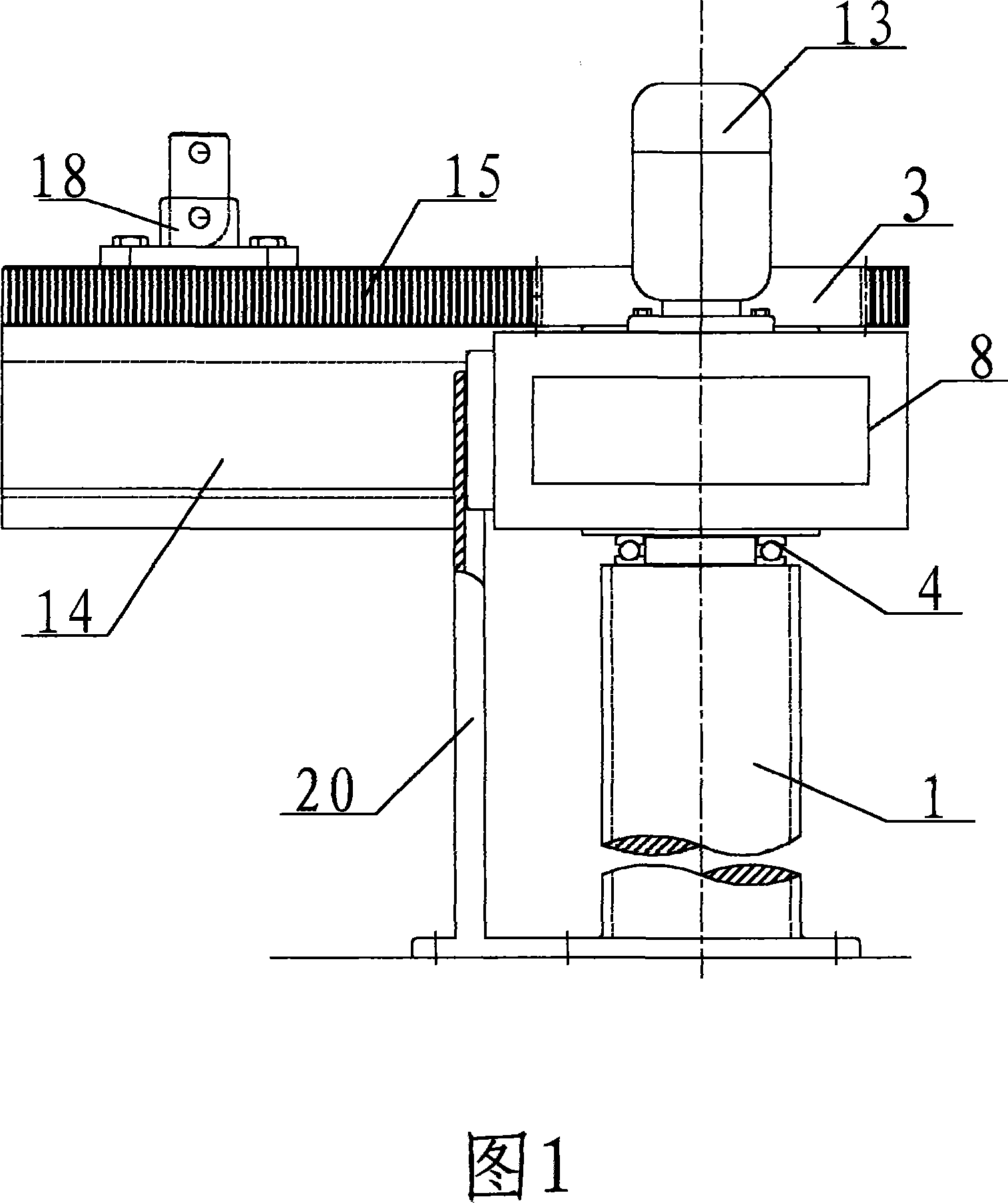
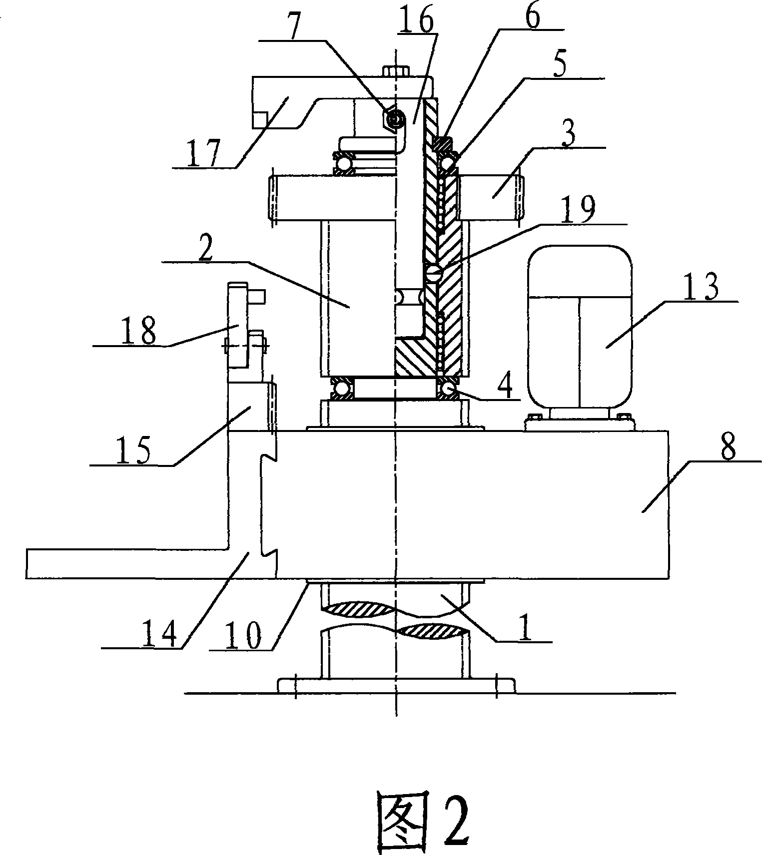
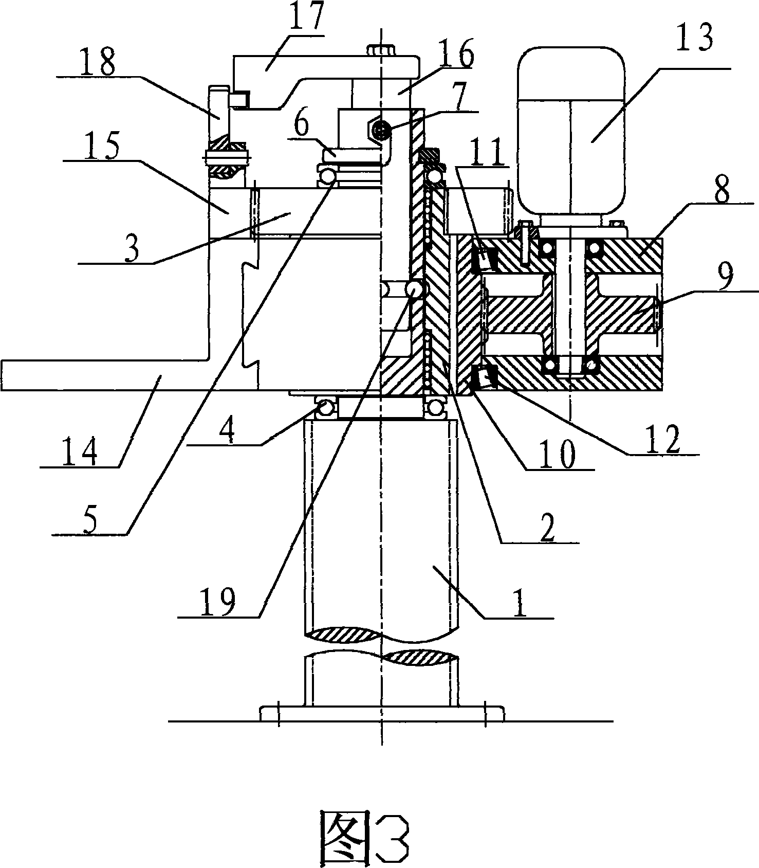
[0038] Embodiment 1: The lifting and translation mechanism of the joint screw shaft, including: the joint screw assembly, the moving box, the bearing platform, the control system, and the vertical guide groove.

[0039]The above-mentioned joint threaded shaft assembly is composed of a fixed threaded shaft 1, a joint threaded sleeve 2, an internal spline gear 3, a lower thrust bearing 4, an upper thrust bearing 5, a snap ring 6, and a magnetic spring bolt 7. The threaded lower end of the fixed threaded shaft 1 is provided with a fixing flange, the upper section is provided as an optical axis section, and the shaft center is provided with a deep hole. The upper ring of the optical axis section is equally divided to form 4 through holes, a circular flat-bottomed groove, and a threaded through hole. Joint threaded sleeve 2, the lower part of the outer circle is set as a thread, and the upper end is set as an external spline. The circle diameter is 0.2±0.1 mm larger than the outer...


PUM


Abstract

The invention discloses a lifting and translation mechanism for an articulated thread spindle, which belongs to the technical field of mechanical design, equipment manufacture and garage. The technical proposal of the lifting and translation mechanism for the articulated thread spindle provided by the invention is the transformation between the lifting operation and the translation operation of a loaded carrying platform and the transformation from the return-stroked translation operation to falling operation by a lesser driving power and the wonderful coordination of the following parts: an articulated thread spindle assembly consisting of a fixed thread spindle, an articulated screwed sleeve, an internal spline gear, an upper thrust bearing and a lower thrust bearing, a snap ring and a magnetic elastic bolt; a moving case body consisted of a moving case body sheathed on the assembly, a power gear and a nut gear; a connected carrying platform and a control system consisted of a control lever, a control arm, a brake and a steel ball. The machine does not stop working during the transformation; the operation is stable and reliable. The technical proposal provided by the invention can be widely applied to the mechanical lifting device, manipulator, and garage construction, etc.

Description

technical field [0001] The invention provides a technical solution for a facility with functions of lifting operation and turning to translation operation, specifically a lifting and translation mechanism of a joint threaded shaft, which relates to the fields of mechanical equipment manufacturing and garage construction. Background technique [0002] The scope of using lifting and moving machinery is very wide, such as factories, construction sites, docks, freight, buildings, residential elevators, garages, etc., and the structure of the facilities usually follows the traditional lifting with wire ropes or rotating or coordinates. The method of moving and falling again, but the method of hoisting with wire ropes for relatively low-height handling and storing goods is not ideal, and it will also cause waste of equipment. Special attention is paid to the construction of garages, especially the situation that there is almost no utilization rate of underground or overhead garage...

Claims


Application Information

Patent Timeline
IPC IPC(8): B65G35/00B65G1/04E04H6/12B66F3/08
Inventor 李国水
Owner FUZHOU GENGYUN PATENT DEV
Why Eureka
Try Eureka