Elevator brake control device

A technology of elevator brakes and control devices, which is applied in transportation, packaging, elevators, etc., can solve the problems of small current drop and difficult detection, and achieve the effects of avoiding service stop, simple structure, and accurate abnormal inspection

Active Publication Date: 2008-07-23
HITACHI LTD +2
View PDF1 Cites 44 Cited by
  • Summary
  • Abstract
  • Description
  • Claims
  • Application Information

AI Technical Summary

Problems solved by technology

[0010] According to technical solution 1, since a discrete detection method is used to detect the excitation current of the brake winding, it is not necessary to continuously measure the excitation current. As a result, it can Solve the above-mentioned problems that detection is difficult due to the small amount of current drop at start-up, and the above-mentioned problems that require high-speed detection of current

Method used


Image

  • Elevator brake control device
  • Elevator brake control device
  • Elevator brake control device

Examples


Embodiment Construction

[0054] An embodiment of the present invention will be described below with reference to the drawings.

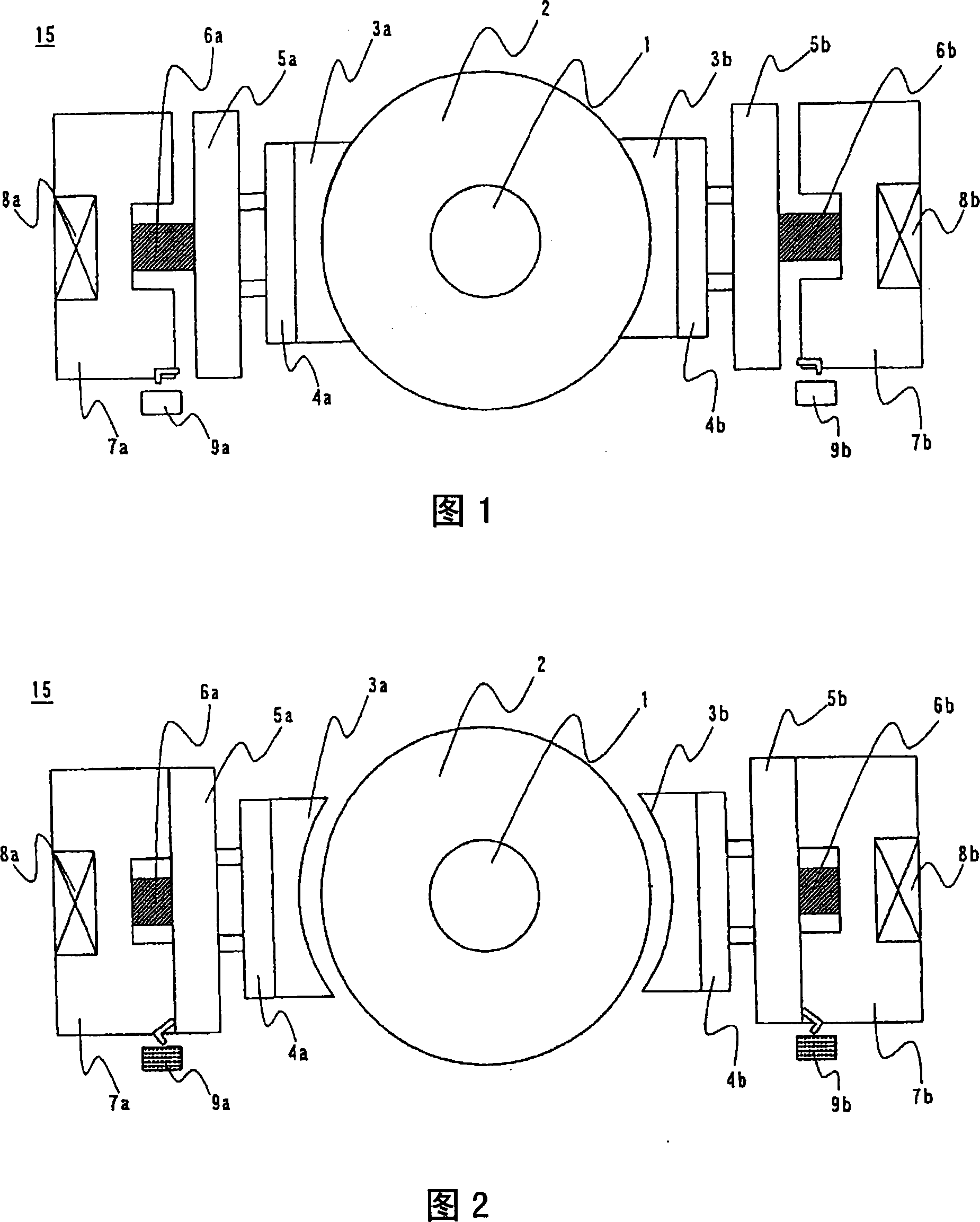
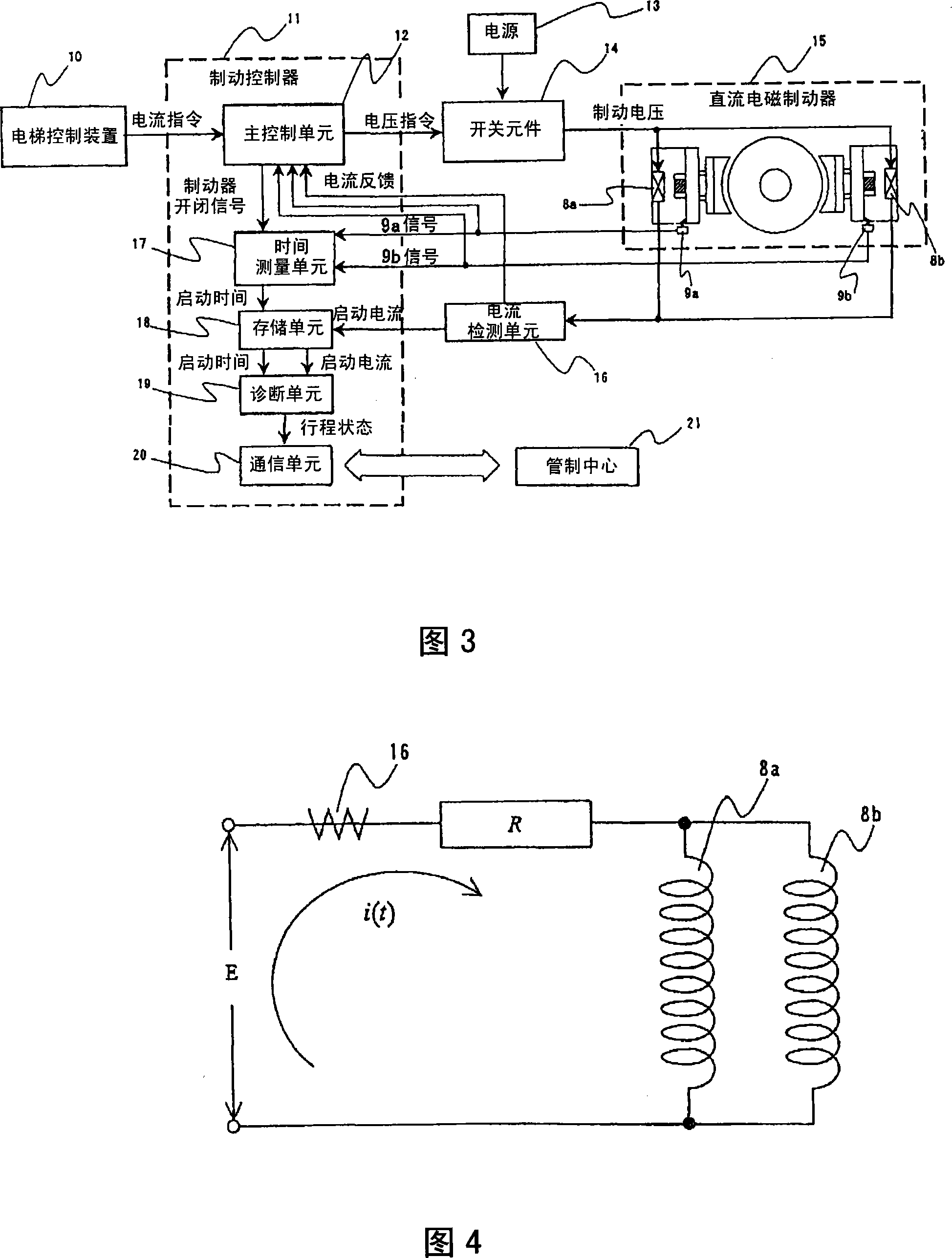
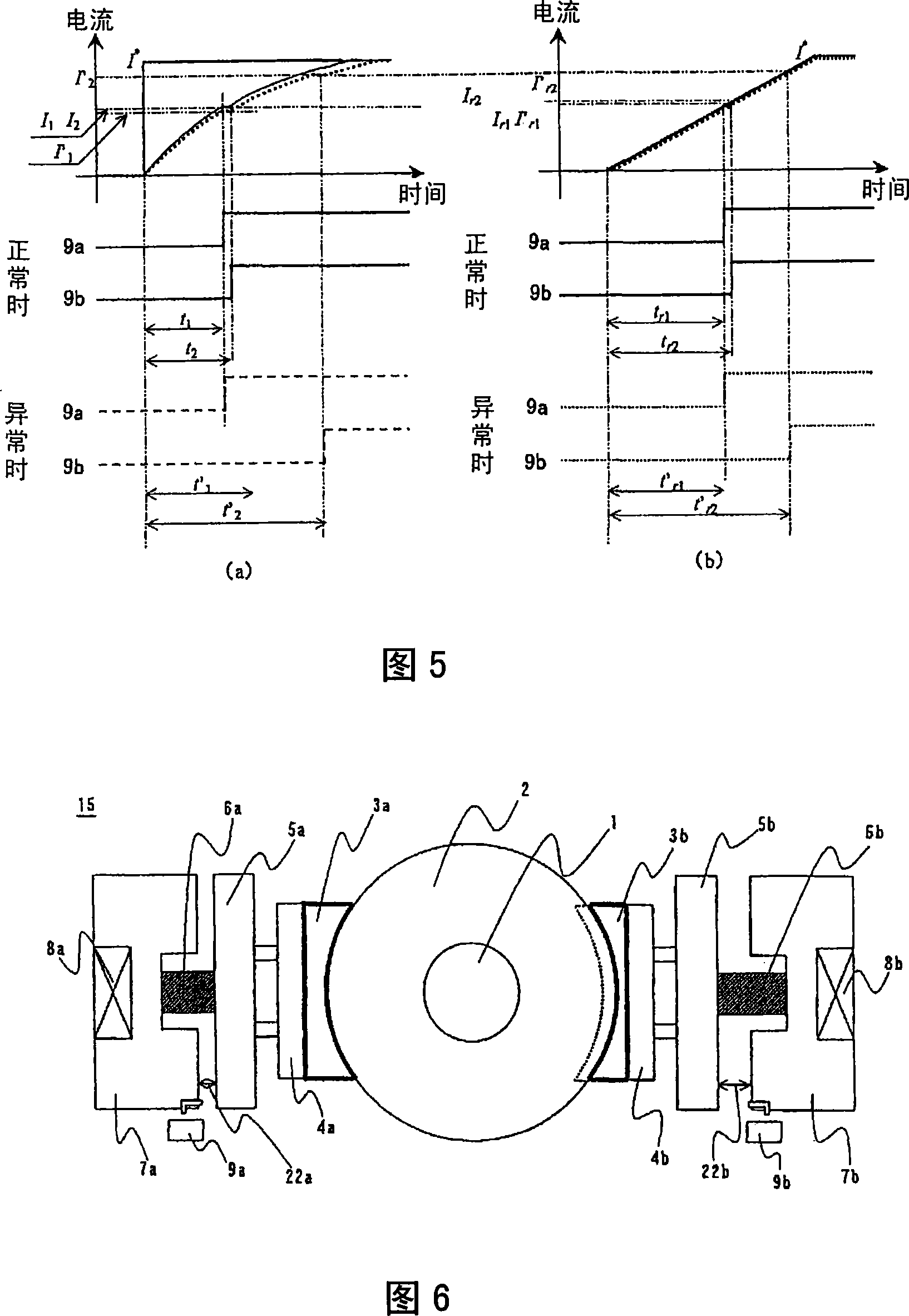
[0055] 1 is an explanatory diagram of the structure (during release) of a brake device provided with a brake check switch, FIG. 2 is an explanatory diagram of the structure (during suction) of the brake device provided with a brake check switch, and FIG. 3 is an overall structure diagram of the present invention, Figure 4 is an electrical circuit diagram of the brake device, Figure 5 is an example diagram showing the brake current response and the timing of the brake check switch, Figure 6 is a diagram of the DC electromagnetic brake when the brake pad is worn, and Figure 7 is a diagram showing the braking As a graph showing the relationship between the current and the stroke, FIG. 8 is a graph showing the relationship between the brake activation current and the stroke when the brake check switch is activated.

[0056] As shown in Figure 1, the DC electromagnetic brake 15 h...


PUM


Abstract

The invention provides an elevator brake control device capable of detecting the abnormity of the direct-current magnetic brake without special device and free from the effect of current staining during the brake operating and the act position of the brake detecting switch. The elevator brake control device comprises: at least above two direct-current magnetic brakes; a brake detecting switches mounted in each direct-current magnetic brake and used for detecting the switching state of the direct-current magnetic brake; a main control unit for commanding the switch of the direct-current magnetic brake; a current detecting unit for detecting the exciting current flowing through the brake coil of the direct-current magnetic brake; a storage cell for storing the normal current value detected by the current detecting unit and a diagnosis cell for diagnosing the state of the direct-current magnetic brake by comparing the normal current value with the abnormal current value.

Description

technical field [0001] The invention relates to an elevator brake control device. In the DC electromagnetic brake of the elevator brake control device, abnormality detection of the DC electromagnetic brake is performed according to the excitation circuit current of the braking electromagnet. Background technique [0002] As such a device, for example, a device is disclosed in Japanese Patent No. 2795152 of Patent Document 1, wherein, as an abnormality detection method of a DC electromagnetic brake, the time-dependent change of the current during the brake operation is continuously measured, Abnormalities are detected by comparing the rising speed of the current value from the start of energization to the start of movement of the movable iron core with the normal rising speed. In addition, for example, Japanese Patent Application Laid-Open No. 3-55342 of Patent Document 2 discloses a device that detects the time when the excitation current drops when the brake operates, and c...

Claims


Application Information

Patent Timeline
Patent Type & Authority Applications(China)
IPC IPC(8): B66B5/02
Inventor 铃木靖孝深田裕纪高山直树古桥昌也佐藤康一筱塚广树松熊利治岩本晃
Owner HITACHI LTD
Why Eureka
Try Eureka