
Loading planning type retaining wall block

A retaining wall, stowage technology, applied in water conservancy projects, artificial islands, underwater structures, etc., can solve the problems of high transportation cost, difficulty, increase project cost, etc., and achieve simple and lightweight construction of walls. Light and easy to move

Inactive Publication Date: 2008-07-23
程卫国
View PDF6 Cites 3 Cited by
  • Summary
  • Abstract
  • Description
  • Claims
  • Application Information

AI Technical Summary

Problems solved by technology

[0004] The main disadvantage of concrete blocks is that it is inconvenient to lift and move manually, so it is more difficult during construction. However, in our country, if the mechanical construction method is used for this form of retaining wall, it is restricted by many conditions: the limitation of the construction site, The strength of the construction company is limited, etc.; secondly, due to the heavy weight of the concrete block, the transportation cost is high; moreover, with the continuous development of the economy, the environment and resources are over-utilized, and the demand for raw materials is in short supply. Cement, gravel and other materials will definitely restrict the development of concrete block reinforced retaining walls in terms of price and raw material supply; fourth, in my country, labor is relatively abundant and cheap
[0005] Moreover, in different engineering application fields and the different foundation soil conditions encountered in practice, different foundation treatments are often carried out to meet the bearing capacity requirements of the selected retaining wall type, which virtually increases the construction cost. Difficulty and cumbersomeness, as well as design changes, increase the cost of the project

Method used


Image

  • Loading planning type retaining wall block
  • Loading planning type retaining wall block
  • Loading planning type retaining wall block

Examples


Embodiment Construction

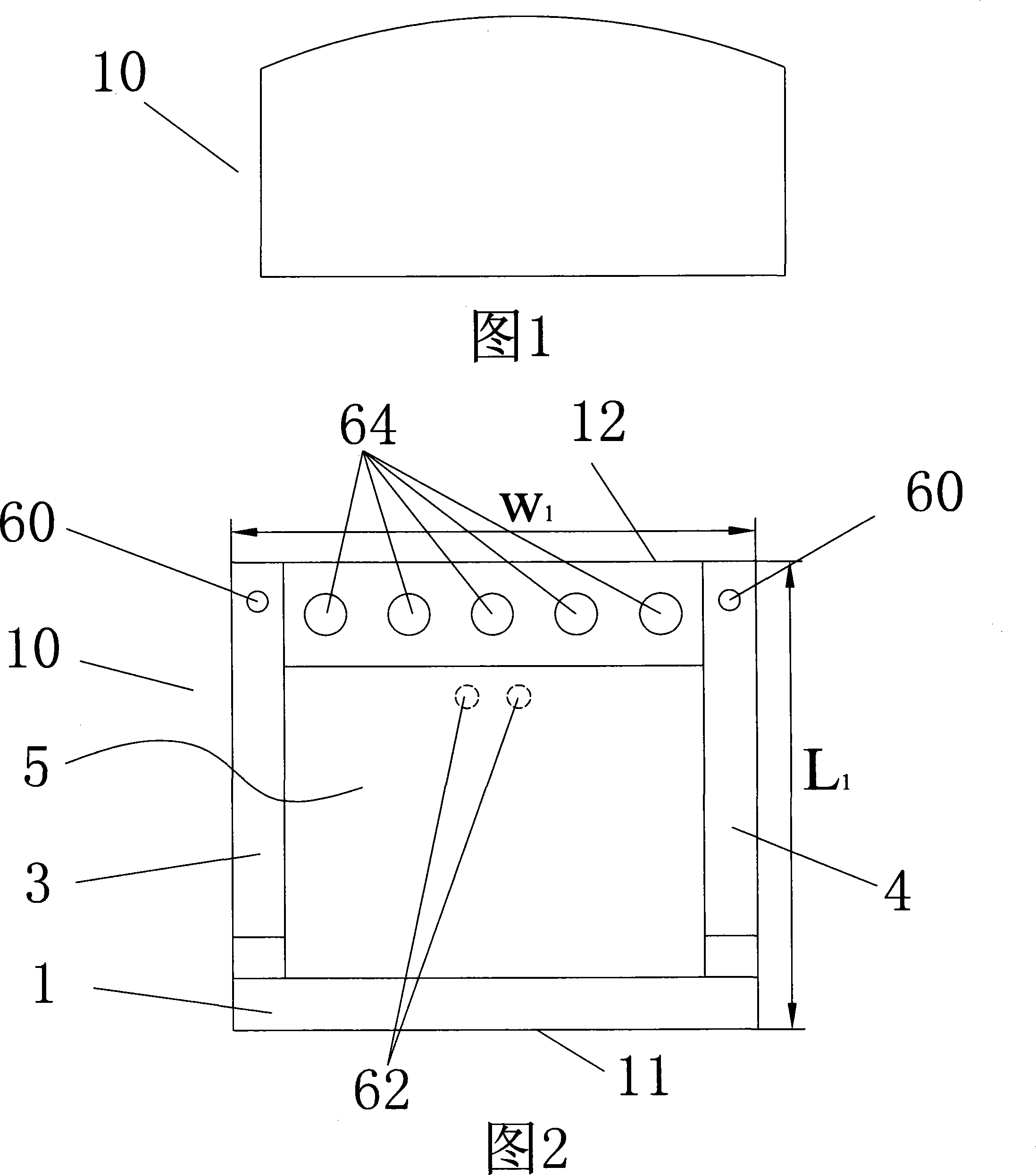
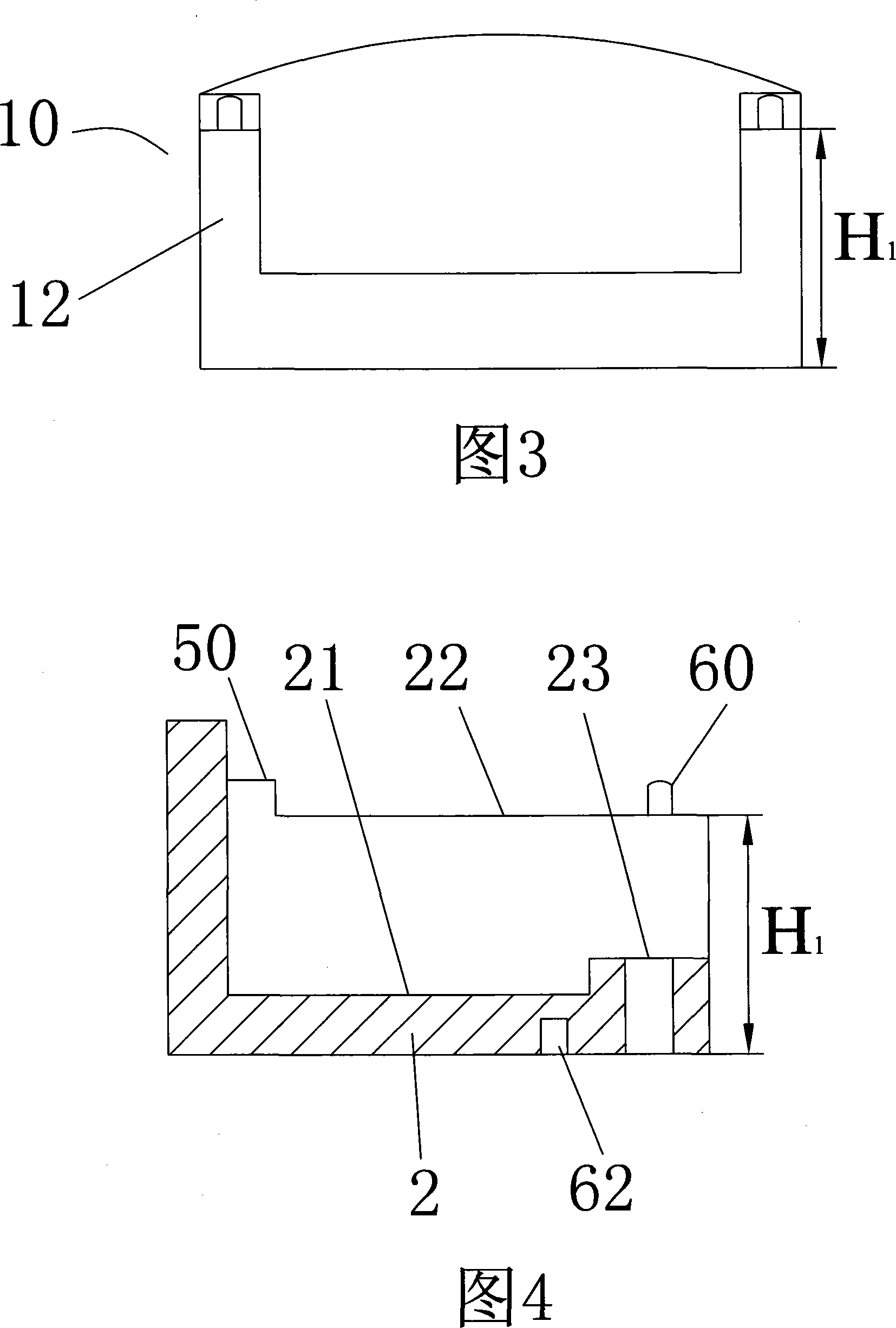
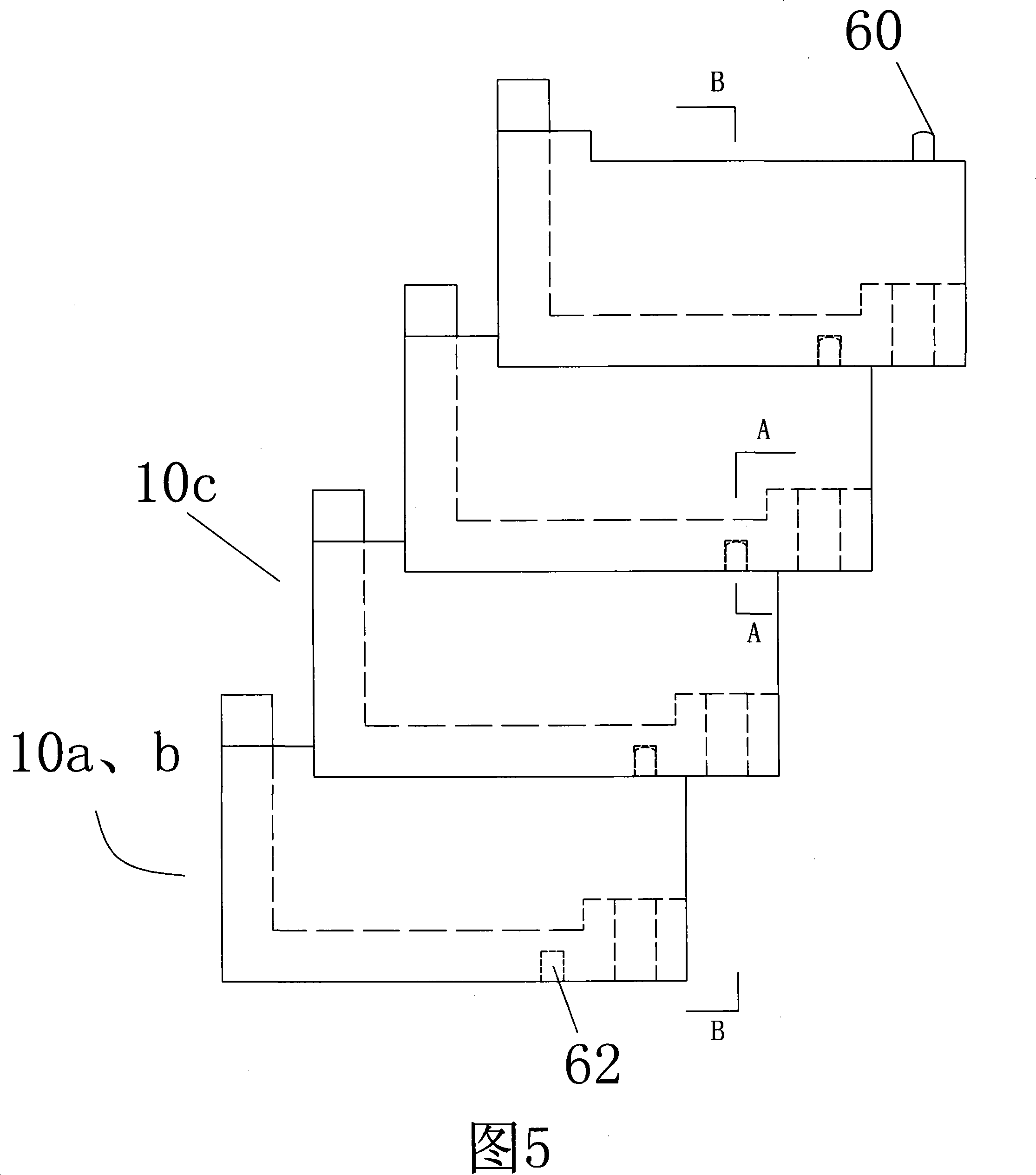
[0025] As shown in FIGS. 1 to 4 , the stowage retaining wall block 10 includes a face wall 1 , a bottom plate 2 , and left and right side walls 3 , 4 . The stowage retaining wall block 10 is made of a suitable polymer material, such as polyethylene that is easy to mold. Width W of stowage retaining wall block 10 1 (Fig. 2) is the distance between the outer surfaces of sidewall 3 and sidewall 4; height H 1 (Fig. 3, 4) is the distance between the bottom surface 21 of base plate 2 and the side wall top surface 22; Length L 1 ( FIG. 2 ) is the distance between the front surface 11 of the face wall 1 and the rear surface 12 of the side walls 3 , 4 . The face wall 1, the bottom plate 2, and the side walls 3 and 4 enclose a backfill cavity 5 (Fig. 2), which can be backfilled with solid backfill such as various soil bodies and construction waste during wall construction. The length, width and depth of the backfill cavity 5 are respectively the block length, width and height minus t...


PUM


Abstract

The invention discloses a stowage type retaining wall block, comprising a bottom plate, a surface wall and a left and a right sidewall; wherein, the surface and the left and right sidewalls are vertical to the bottom plate of the block; a cavity is formed among the bottom plate, the surface wall and the left and right sidewalls; solid backfill is filled in the cavity while in construction; a plurality of retaining wall blocks are connected with each other by shape matching, so as to form a wall body. The stowage type retaining wall block has the advantages that the product weight is relatively light; the carrying, lifting and long distance transportation in constructing process is convenient; different materials can be backfilled in the surface layer structure of the wall surface; the block weight is increased to meet the requirement for stabilization; the selection of backfill can adopt the solid waste such as building waste and coal ash, which can effectively reduce the effect of waste on environment; the wall body building method is relatively simple.

Description

technical field [0001] The invention relates to a building block of a retaining wall, in particular to a load-bearing retaining wall block made of synthetic materials such as polymers. Background technique [0002] At present, reinforced retaining walls are more and more widely used, but the main form is still prefabricated concrete panels without structural requirements as the surface layer of reinforced retaining walls. The size of such large panels is relatively large. Large-scale lifting equipment is often required during construction, which brings certain difficulties and difficulties to the construction. In foreign countries, since the 1980s, concrete blocks have been widely used as the panels of reinforced retaining walls. This panel structure has strong flexibility and can be suitable for different foundations under different load conditions deformation, and the block panel itself has strong adjustability, and has certain structural functions, for example, setting s...

Claims


Application Information

Patent Timeline
IPC IPC(8): E02D29/02
Inventor 程卫国龚丽飞郭军辉何辅友朱友群
Owner 程卫国
Learn More