Phase type probe sensing structure

A phase type, probe technology, applied in the direction of point coordinate measurement, electromagnetic measurement devices, etc., can solve the problems of large measurement force, large cantilever beam, and errors, so as to improve measurement sensitivity, improve defects, reduce The effect of force

Inactive Publication Date: 2008-07-23
IND TECH RES INST
View PDF0 Cites 1 Cited by
  • Summary
  • Abstract
  • Description
  • Claims
  • Application Information

AI Technical Summary

Problems solved by technology

[0005] 1. The large size of the cantilever beam prevents miniaturization of the sensing structure
[0006] 2. Cannot connect smaller probe handles
[0007] 3. The measurement force is large, and it is easy to damage the object under test
[0008] 4. Limited by the vibration direction of the probe, it has anisotropy (Anisotropy), and there will be errors in two-dimensional measurement

Method used


Image

  • Phase type probe sensing structure
  • Phase type probe sensing structure
  • Phase type probe sensing structure

Examples


Embodiment Construction

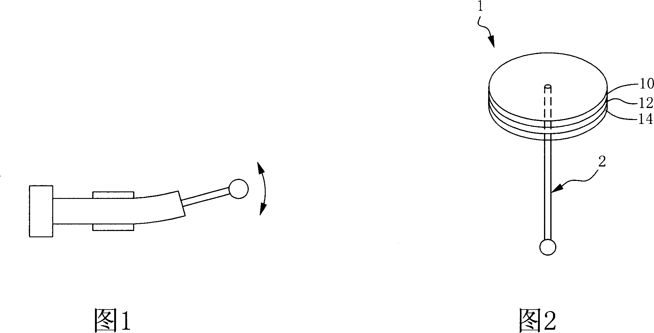
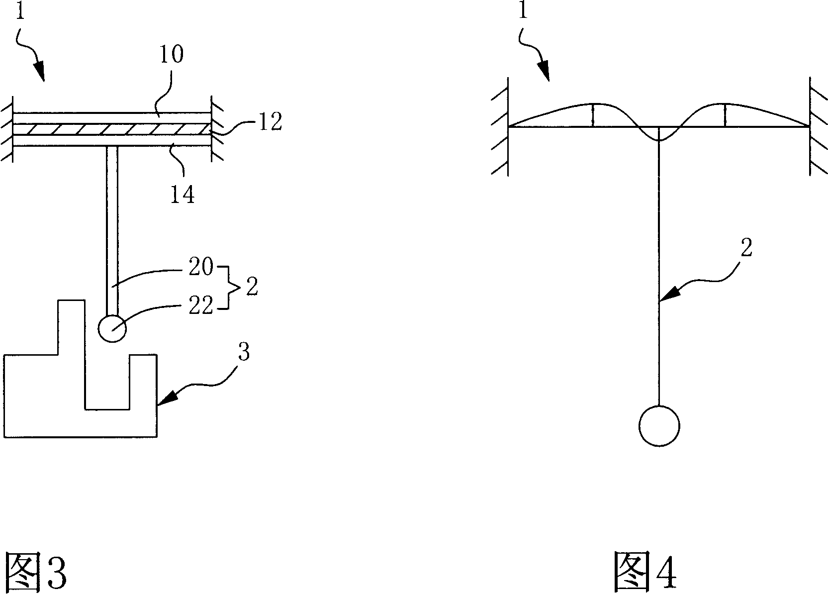
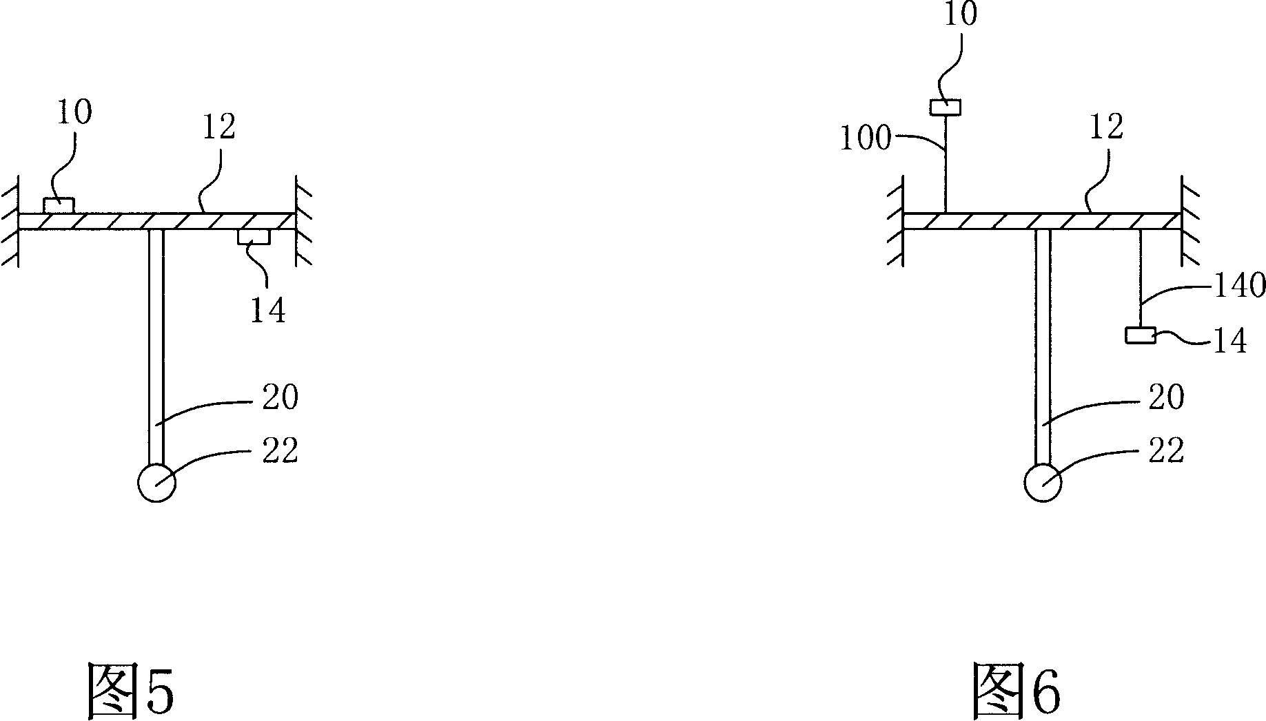
[0044] Please refer to FIG. 2 and FIG. 3 , which are perspective and cross-sectional views of the phase probe sensing structure of the present invention, respectively. The phase probe sensing structure 1 is composed of an actuating unit 10, a substrate 12 and a sensing unit 14, and the substrate 12 is further connected with a probe 2, and the probe 2 includes a probe handle 20 and a probe head 22 , one end of the probe handle 20 is connected to the substrate 12 , and the other end is connected to the probe head 22 . Structurally, in a preferred embodiment of the present invention, the actuating unit 10 is a piezoelectric actuating film, the sensing unit 14 is a piezoelectric sensing film, and the substrate 12 It is also a thin-filmed low-loss material, such as a silicon wafer, and the actuating unit 10 and the sensing unit 14 are respectively attached to two sides of the substrate 12 .

[0045] When measuring, the user activates the actuating unit 10 with a voltage of a speci...


PUM

PropertyMeasurementUnit
Diameteraaaaaaaaaa
Thicknessaaaaaaaaaa

Abstract

The invention relates to a phase probe sensing structure, which is connected with a probe; the phase probe sensing structure comprises an actuating unit; a base material which is connected with the actuating unit; and a sensing unit which is connected with the base material; wherein the actuating unit can generate vibration in a certain frequency so as to make the phase probe sensing structure resonate in a scheduled mode; therefore the phase probe sensing structure has the advantages that: the measurement sensitivity of the probe can be improved; the force implemented on the object under test while in measuring can be lowered significantly; and the shortcomings of the prior art can be solved effectively.

Description

technical field [0001] The present invention relates to a phased probe sensing structure, and more particularly to a phased probe sensing structure resonating in a predetermined mode. Background technique [0002] As daily scientific and technological products become smaller and smaller, the demand for dimensional measurement of tiny components is increasing year by year. These tiny components include microlenses, biomedical microfluidics, high-efficiency automotive fuel nozzles, optical fiber connectors for optical communications, and high-aspect-ratio micro-electromechanical components. Process structure; however, the measurement accuracy of existing measurement technologies cannot meet the three-dimensional measurement requirements of these components. Although the scanning probe microscope (SPM) has nanometer-level resolution, the measurement range is 100 microns (μm) x 100 microns (μm) x 5 microns (μm), and the test piece often needs to have Due to the flat surface, th...

Claims


Application Information

Patent Timeline
IPC IPC(8): G01B7/012G01B7/016
Inventor 吴乾埼许正治翁汉甫林志明
Owner IND TECH RES INST
Why Eureka
Try Eureka