Apparatus comprising a recursive delayer and method for measuring a phase noise

Active Publication Date: 2012-10-11
ADVANTEST CORP
View PDF3 Cites 23 Cited by
  • Summary
  • Abstract
  • Description
  • Claims
  • Application Information

AI Technical Summary

Benefits of technology

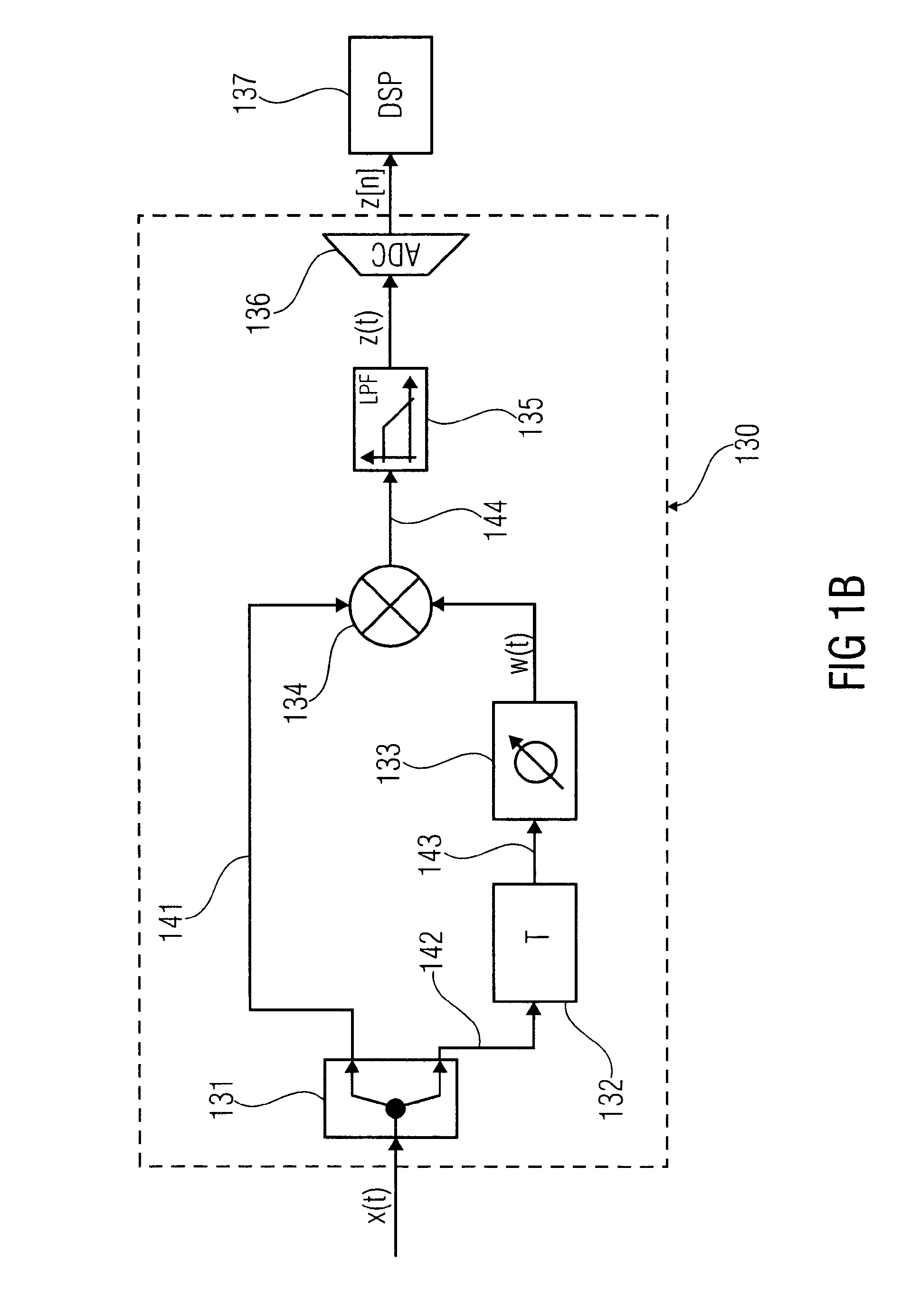
[0007]Embodiments of this present invention provides a solution to the challenges inherent in high precision measurement of phase noise. In one exemplary embodiment, high precision measurement of phase noise can be achieved by using long delay lines improving measurement sensitivity without adding further complexity or additional cost to the phase noise measurements. Embodiments of the invention avoid the use of an adjustable phase shifter which is complex to handle in discriminator-based phase noise measurements. Embodiments of the invention may not require high precision external sources providing a reference phase. Embodiments of the invention may increase the phase noise measurement sensitivity by means of a recursive delay line architecture, which exploits a feedback path to enhance the measurement sensitivity. Some embodiments of the invention show a gain in measurement sensitivity of about 40 dB over conventional delay line discriminators.

Problems solved by technology

Phase noise of signal sources is a severe cause of performance degradation in communication systems.
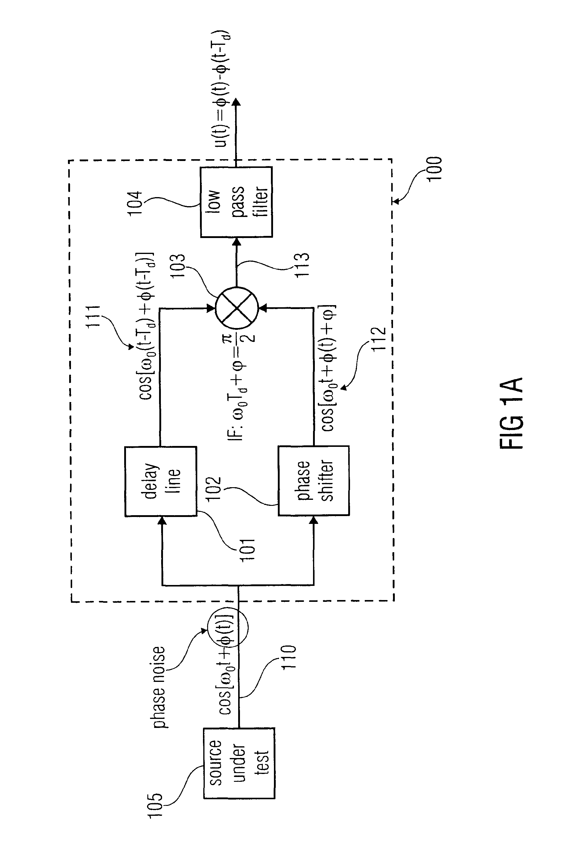
However, delay line discriminators are known to suffer severe sensitivity loss for close-in phase noise measurements showing a poor performance, due to the non-zero correlation between the phase noise waveform and its delayed version.
The poor performance for close-in phase measurements is due to the strong attenuation that low frequency components undergo when passing through the delay line discriminator.
This attenuation can be so strong that the signal falls below the noise floor, making the phase noise measurement virtually impossible.
However, long analog delay lines are difficult to build.

Method used


Image

  • Apparatus comprising a recursive delayer and method for measuring a phase noise
  • Apparatus comprising a recursive delayer and method for measuring a phase noise
  • Apparatus comprising a recursive delayer and method for measuring a phase noise

Examples


Embodiment Construction

[0038]Reference will now be made in detail to the preferred embodiments of the present invention, examples of which are illustrated in the accompanying drawings. While the invention will be described in conjunction with the preferred embodiments, it will be understood that they are not intended to limit the invention to these embodiments. On the contrary, the invention is intended to cover alternatives, modifications and equivalents, which may be included within the spirit and scope of the invention as defined by the appended claims. Furthermore, in the following detailed description of embodiments of the present invention, numerous specific details are set forth in order to provide a thorough understanding of the present invention. However, it will be recognized by one of ordinary skill in the art that the present invention may be practiced without these specific details. In other instances, well-known methods, procedures, components, and circuits have not been described in detail ...


PUM


Abstract

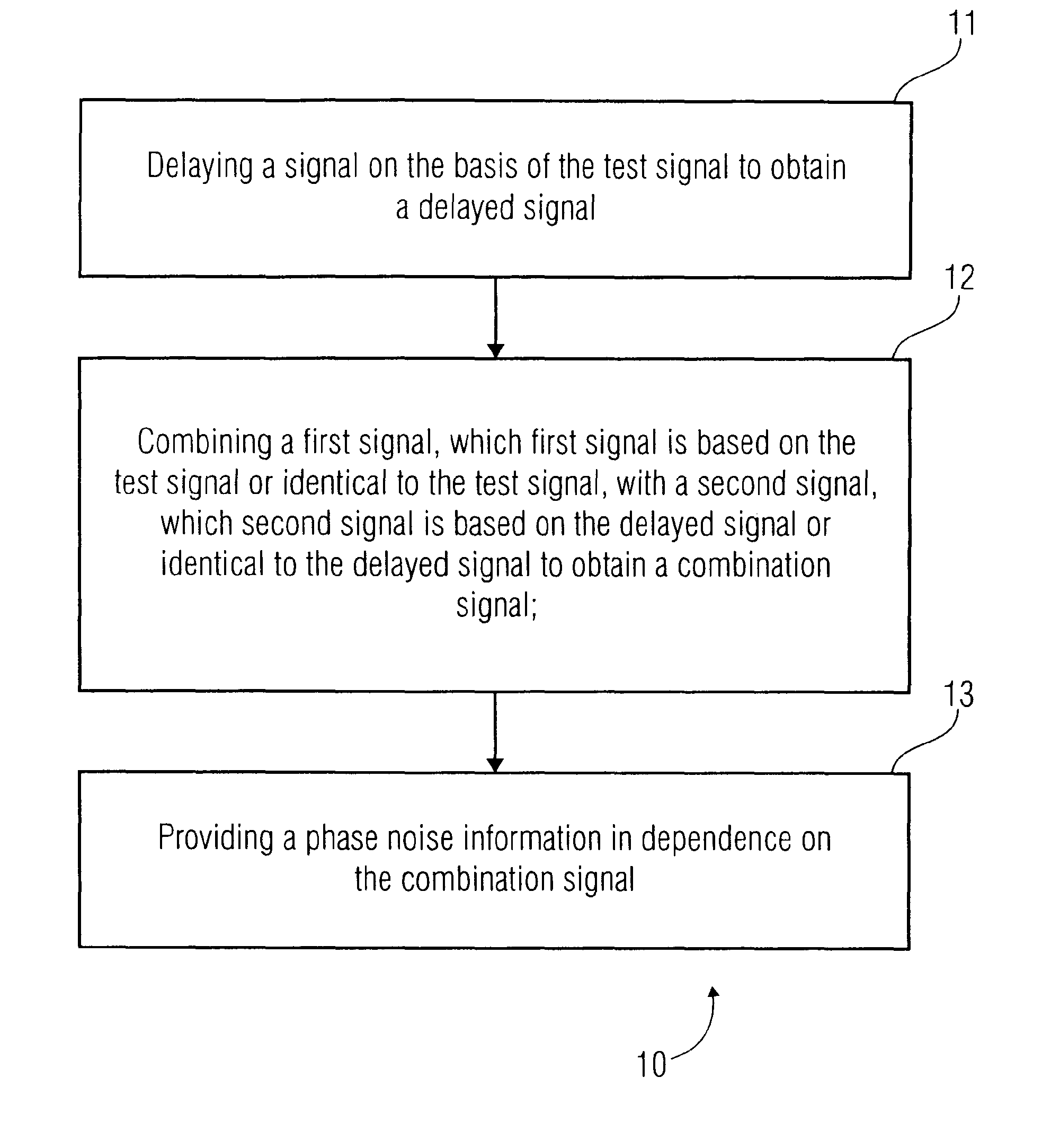
Embodiments of the invention provide an apparatus for measuring a phase noise of a test signal. The apparatus comprises a recursive delayer, a combiner and a phase noise determinator. The recursive delayer is configured to provide a delayed signal on the basis of the test signal. The combiner is configured to combine a first signal with a second signal to provide a combiner output signal. The first signal is based on the test signal or a signal identical to the test signal. The second signal is based on the delayed signal or a signal identical to the delayed signal. The phase noise determinator is configured to provide a phase noise information that depends on the combiner output signal.

Description

CROSS-REFERENCES TO RELATED APPLICATIONS[0001]This application is a Continuation of and claims priority to International Application No. PCT / EP2009 / 007545, filed on Oct. 21, 2009, titled “APPARATUS COMPRISING A RECURSIVE DELAYER AND METHOD FOR MEASURING A PHASE NOISE,” by Pausini, et al., which is herein incorporated by reference.TECHNICAL FIELD[0002]The present disclosure relates generally to the field of phase noise measurement and more specifically to the field of phase noise measurement with a recursive delayer.BACKGROUND[0003]Phase noise of signal sources is a severe cause of performance degradation in communication systems. Thus, in the production phase of radio frequency (RF) chips that are configured to handle electrical, optical and / or electromagnetic signals in the radio frequency range (3 KHz up to 300 THz), it is very important to accurately measure the phase noise of the device under test (DUT), meanwhile keeping the cost of test (COT) as low as possible.[0004]Delay lin...

Claims


Application Information

Patent Timeline
IPC IPC(8): G01R29/26
CPCG01R31/31709
Inventor PAUSINI, MARCORIVOIR, JOCHEN
Owner ADVANTEST CORP
Why Eureka
Try Eureka