Method and device for detecting optical element laser damage threshold

A technology of laser damage threshold and optical components, which is applied in measuring devices, fluorescence/phosphorescence, and material analysis through optical means, and can solve problems such as inability to directly observe the morphology of the irradiated area online and unspecified discrimination methods

Active Publication Date: 2008-07-23
CHINA INSTITUTE OF ATOMIC ENERGY
View PDF0 Cites 33 Cited by
  • Summary
  • Abstract
  • Description
  • Claims
  • Application Information

AI Technical Summary

Problems solved by technology

The above five methods for judging damage all have the disadvantage of not being able to visually observe the morphology of the irradiated area online.
In Liu Qiang, Lin Libin, Zu Xiaotao, Gan Rongbing, Intense Laser Radiation Damage Discrimination Method, Laser Journal, 2002, 23(4), it is mention

Method used


Image

  • Method and device for detecting optical element laser damage threshold

Examples


Embodiment Construction

[0013] Below in conjunction with accompanying drawing, the present invention will be further described.

[0014] Implementation column 1:

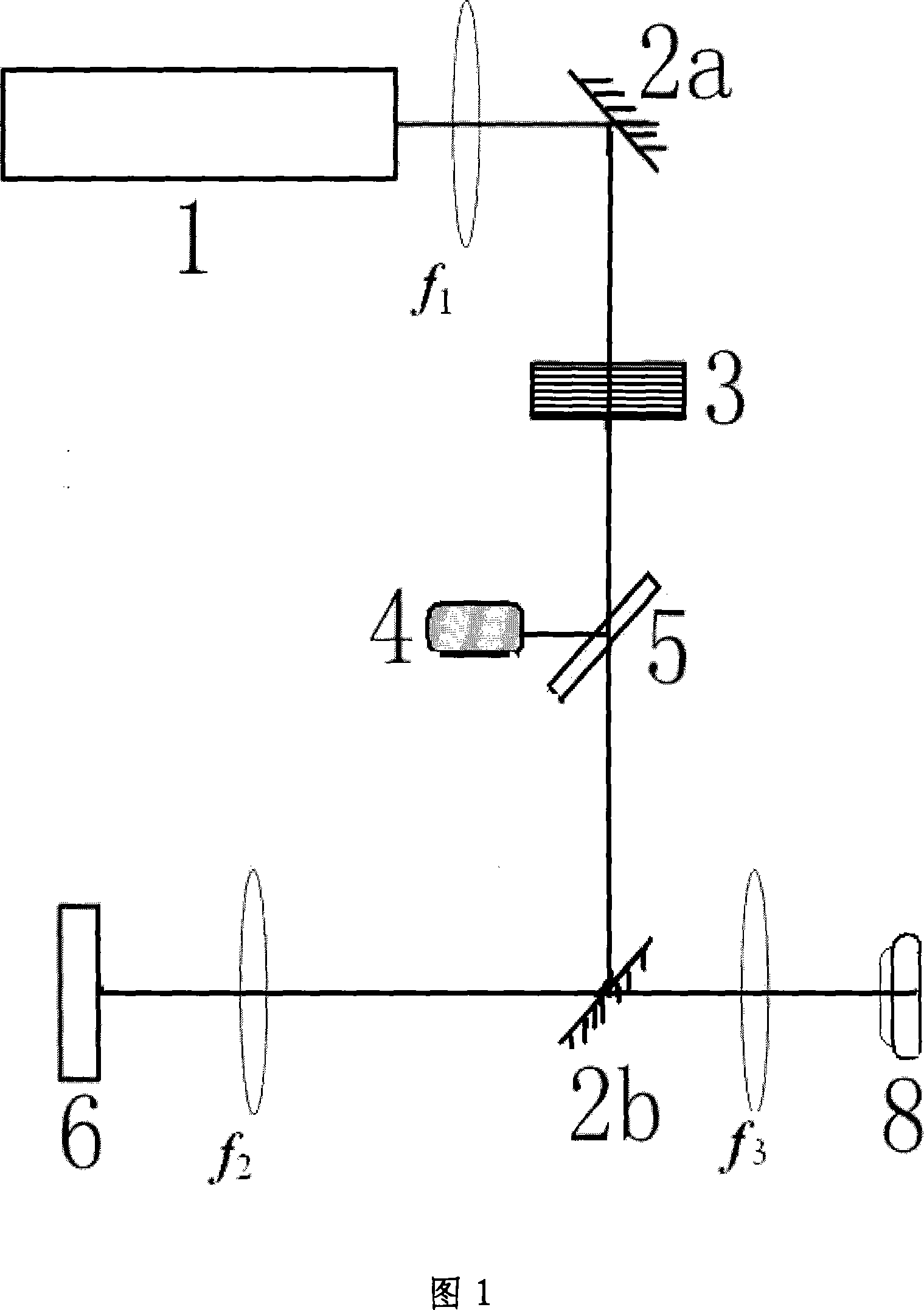
[0015] As shown in Figure 1, the KrF laser (1) emits laser light with a pulse width of 24 ns, uniformly irradiates the area with a diameter of 2 mm on the surface of the optical element to be tested (6) at an incident angle of 0°, and the lens group f 1 , f 2 The uniformly distributed cross-sectional image of the beam is transmitted to the front surface of the optical element (6) to be tested, and the laser light excites the fluorescent spot on the surface of the intact optical element, and passes through the lens f 2 , f 3 The composed fluorescence microscope is magnified by 3 times and imaged on the CCD array detector (8), so as to observe the change of the surface of the optical element (6) to be tested, and judge whether the optical element (6) to be tested is damaged. The laser energy output by the KrF laser (1) is attenuated by th...


PUM


Abstract

The invention provides a laser damage threshold detection method of optical component and a relative device, which utilizes the laser generated by a laser device to radiate on the surface of an object optical component to generate fluorescent light, to detect the surface morphology change of the optical component, wherein the laser device is KrF laser, and the invention detects the distortion of surface fluorescent light strength distribution on the optical surface to detect the surface morphology change of the optical component. The invention can directly detect damage generation and develop, with wide application for surface damage online tests on ultraviolet optical component and high sensitivity.

Description

technical field [0001] The invention belongs to a method for detecting optical element damage, and in particular relates to a method and a device for detecting the laser damage threshold of an optical element by using a KrF laser to irradiate the surface of the optical element to excite fluorescence imaging. Background technique [0002] In a high-power laser system, there are a large number of optical components, and the ability of these optical components to resist light damage is closely related to the normal operation of the system. The generation of damage will lead to the degradation of beam quality, the thermal effect at the damage point may cause the explosion of optical components, and the diffraction of the beam at the damage point will cause damage to other optical components. The radiation damage of optical components is the result of the interaction between components and strong laser light. An important indicator for judging the quality of optical components is...

Claims


Application Information

Patent Timeline
IPC IPC(8): G01N21/64G01N21/958
Inventor 高智星汤秀章向益淮
Owner CHINA INSTITUTE OF ATOMIC ENERGY
Why Eureka
Try Eureka