Method of manufacturing rotor of electric motor and electric motor

A manufacturing method and motor technology, which is applied in the field of motors, can solve the problems of peeling, lower mechanical strength, and higher manufacturing costs, and achieve the effects of preventing peeling, improving reliability, and improving manufacturing quality

Inactive Publication Date: 2008-07-23
FANUC LTD
View PDF2 Cites 16 Cited by
  • Summary
  • Abstract
  • Description
  • Claims
  • Application Information

AI Technical Summary

Problems solved by technology

[0005] However, in conventional motors, since the pair of end plates are fixed by a fastening mechanism such as screws or rivets, there are problems that the number of parts increases and the assembly of the pair of end plates is troublesome, resulting in high manufacturing costs.
[0006] In addition, in the conventional motor, although the end plate and the end portion of the permanent magnet are in contact, there may be a gap between the end plate and the end surface (end surface of the thin plate) of the laminated core without contact. If a gap occurs, when the inner rotor is inserted into the stator during assembly of the motor, the outer peripheral surface of the rotor and the inner peripheral surface of the stator may come into sliding contact and each laminated thin plate of the multilayer structure may be peeled off.
In particular, in large motors for high output that are suitable for machine tools, etc., there is a problem that the mechanical strength decreases due to peeling of each laminated sheet
[0007] Apparently, the problem of creating a gap between the end plate 55 and the laminated core 50 is that, as shown in FIG. The warping of the lamination core 50, or as shown in FIG.

Method used


Image

  • Method of manufacturing rotor of electric motor and electric motor
  • Method of manufacturing rotor of electric motor and electric motor
  • Method of manufacturing rotor of electric motor and electric motor

Examples


Embodiment Construction

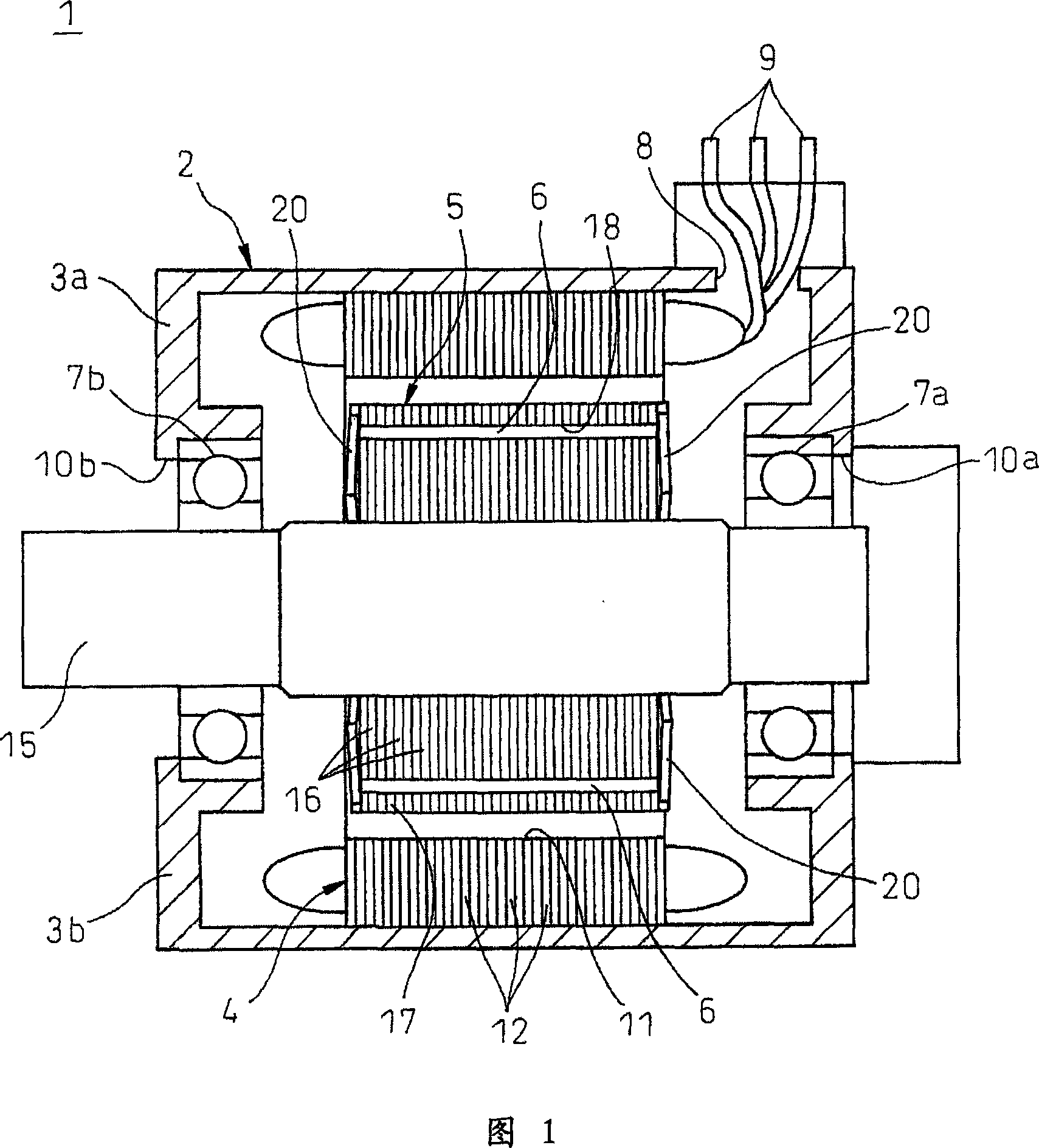
[0037] Specific examples of embodiments of the present invention will be described in detail below using the drawings. FIG. 1 shows an embodiment of a motor according to the present invention. The motor 1 of the present embodiment includes: a cylindrical casing 2; an outer stator 4 provided annularly along the inner peripheral surface of the casing 2; and an inner rotor (motor rotor) rotatably arranged inside the outer stator 4. 5; a plurality of magnets 6 embedded at equal intervals in the circumferential direction of the inner rotor 5; and a pair of bearings 7a, 7b pivotally supporting the rotating shaft 15 of the inner rotor 5 on both left and right sides.

[0038] The housing 2 is made of a non-magnetic material such as aluminum, and is composed of an upper housing 3a and a lower housing 3b having a split structure. The upper and lower pairs of housings 3a and 3b can be assembled integrally after disposing the inner rotor 5 inside the outer stator 4 . Three electric wire...


PUM


Abstract

A method of manufacturing a rotor of an electric motor, the rotor including a laminated core of multilayer structure formed from electromagnetic thin plates laminated in an axial direction of a rotational shaft, and a pair of end plates disposed on opposite sides in the axial direction of the laminated core, and the rotor being rotatably disposed in an inside of a stator, the method including: fitting the rotational shaft into an insertion hole formed in a center region of the end plates having elasticity in a direction of plate thickness; positioning the end plates at specified position on the rotational shaft; and abutting either one of the end plates in elastically deformed state to at least one end of the laminated core.

Description

technical field [0001] The present invention relates to a method of manufacturing a motor rotor which is rotatably arranged inside a stator and which is suitable for use in machine tools, automatic machines, press machines, injection molding machines, etc., and an electric motor. Background technique [0002] Generally, for an inner-rotor-type electric motor in which a motor rotor is arranged inside a stator, the motor rotor includes: a rotating shaft; A pair of end plates arranged on both sides in the axial direction of the laminated core are provided with the rotation shaft inserted into an insertion hole formed in the central portion to communicate with each other. [0003] The motor disclosed in Japanese Patent Application Laid-Open No. 9-233750 includes an inner rotor in which permanent magnets longer than the axial dimension of the laminated core are embedded, and one of the two ends of the laminated core is arranged. At least one of the pair of end plates is pressure...

Claims


Application Information

Patent Timeline
Patent Type & Authority Applications(China)
IPC IPC(8): H02K15/02H02K15/03H02K1/27H02K21/14
CPCH02K15/02Y10T29/49012
Inventor 冈本敬古屋刚
Owner FANUC LTD
Why Eureka
Try Eureka