
Shrapnel on circuit board and electromagnetic shielding assembly

A technology of circuit boards and shrapnel, applied in the direction of magnetic field/electric field shielding, printed circuit, circuit arrangement on support structure, etc., can solve problems such as fracture, shrapnel 2 damage, bending, etc., to avoid bending deformation or fracture, and ensure Elasticity, the effect of avoiding tin creeping

Inactive Publication Date: 2008-07-23
陈惟诚
View PDF0 Cites 2 Cited by
  • Summary
  • Abstract
  • Description
  • Claims
  • Application Information

AI Technical Summary

Problems solved by technology

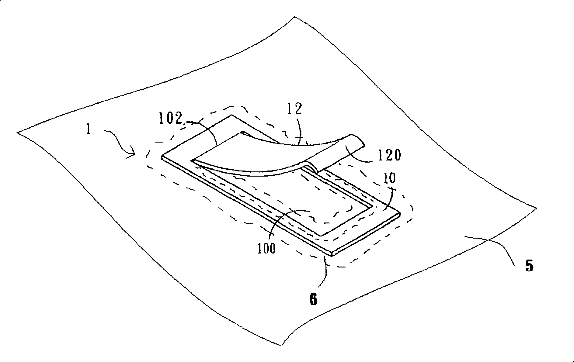
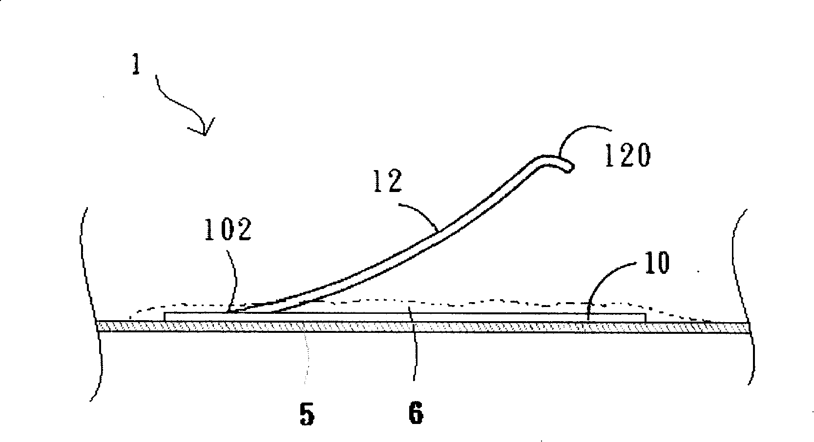
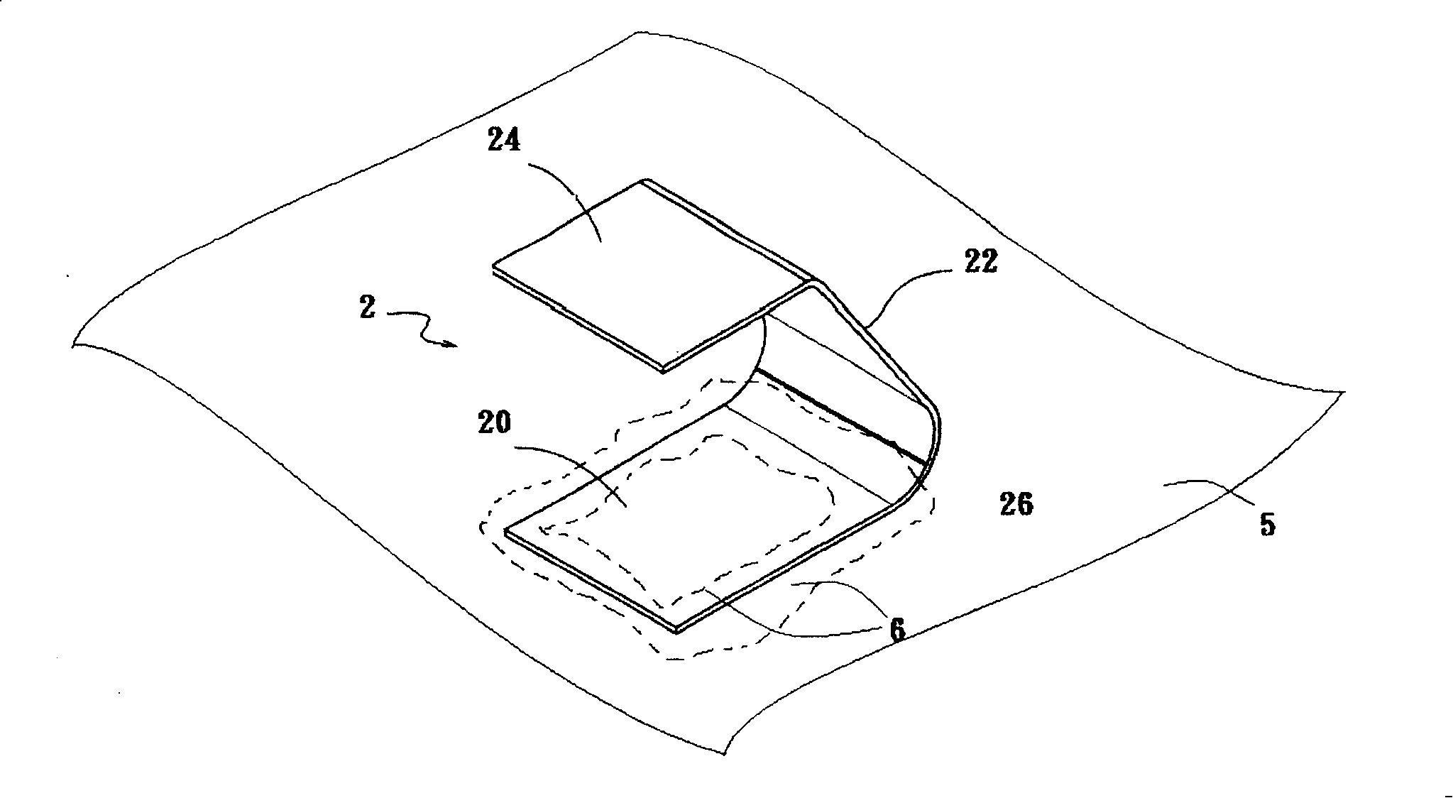
[0006] When connecting with a circuit board 5, first use vacuum suction equipment to absorb on the abutting section 24 of the shrapnel 2, and move the shrapnel 2 to a specific position on the circuit board. During the transfer, the shrapnel 2 may be damaged due to inadvertent collision. A lateral thrust causes the elastic arm 22 or the abutting section 24 to deform laterally. On the other hand, if excessive force is applied to press the abutting section 24 downward, the elastic arm 22 will , there may be an irreversible deformation at the junction of the elastic arm 22 and the welding section 20. As the deformation increases, the stress required for the deformation will be smaller. Under such a vicious cycle, the shrapnel 2 will eventually be completely damaged; the shrapnel 2 will be welded When being fixed on the circuit board 5, the solder 6 may also climb to the soldering section 20 and produce a stress concentration point 26 with a smaller radius of curvature between the soldering section 20 and the elastic arm 22, especially when the elastic arm 26 is deformed due to careless operation. When the arm is tilted up in reverse, it is easy to break and bend at the stress concentration point 26

Method used


Image

  • Shrapnel on circuit board and electromagnetic shielding assembly
  • Shrapnel on circuit board and electromagnetic shielding assembly
  • Shrapnel on circuit board and electromagnetic shielding assembly

Examples


Embodiment Construction

[0030] The foregoing and other technical contents, features and effects of the present invention will be clearly presented in the following detailed description in conjunction with preferred embodiments and accompanying drawings.

[0031] Such as Figure 4-7 As shown, the shrapnel 3 on the circuit board provided by a preferred embodiment of the present invention is an integrally formed metal sheet, which includes a shrapnel body 31, and the upper and lower sides of the shrapnel body 31 are two opposite wings 310 (such as Figure 4 As shown), the two side wings adjacent to the left and right sides are two end edges 312. In this embodiment, the side wings 310 and the end edges 312 are perpendicular to each other to form a rectangle; Arm 32; a welding section 30 is folded downwards from two opposite side wings 310 of the spring body 31, and the welding section 30 can be divided into a welding base 300 corresponding to the spring body 31 and a welding base 300 extending from the w...


PUM


Abstract

The invention discloses a striking flake which is welded on a circuit board, the striking flake comprises a striking flake body which is provided with two relative flanks and two end margins which are near the two flanks, a flexible arm which is extended from one of the two end margins and takes an included angle with the striking flake body to extend and two reverse-folded welding segments which are respectively extended from the two flanks of the striking flake body and reverse-folded to the corresponding striking flake body. The invention is mounted up by the reverse-folded welding segments, which can effectively prevents the flexible arm from folding-deforming or fracturing and can be used for a long time. The invention also discloses an electromagnetic shielding assembly with the above striking flake structure.

Description

technical field [0001] The invention relates to a shrapnel welded on a circuit board; in addition, the invention also relates to an electromagnetic shielding assembly having the above-mentioned shrapnel structure. Background technique [0002] Generally, in the electronic device, there is usually a shrapnel made of bent metal material, which is soldered and fixed on the circuit board by surface mount technology (SMT). The elastic force of the shrapnel itself after being bent by the metal material can be used as a For example, the ground terminals of two circuit boards are connected to each other to avoid potential differences; another example is to set up a metal shell to shield some circuits and components from electromagnetic wave interference. [0003] Such as figure 1 , 2 As shown, the common shrapnel 1 is a metal sheet formed by stamping, so that only a short side 102 of the central rectangular part is connected with the welding section 10 of the peripheral part, and ...

Claims


Application Information

Patent Timeline
IPC IPC(8): H05K9/00H05K7/02H05K1/00H01R12/00
Inventor 陈惟诚
Owner 陈惟诚
Learn More