Skin wound stiching instrument and stiching method thereof

A suturing device and wound technology, applied in the medical field, can solve problems such as difficult to achieve equivalence, reverse, balance, difficulty, and increased pain for patients, and achieve uniform and reasonable distribution of skin force, reduced manufacturing cost, and novel structure Effect

Active Publication Date: 2008-07-30
江苏泰应生物科技有限公司
View PDF2 Cites 23 Cited by
  • Summary
  • Abstract
  • Description
  • Claims
  • Application Information

AI Technical Summary

Problems solved by technology

[0002] In the prior art, after the operation of the patient, the wound is sutured with thread, which not only consumes the energy of the doctor, but also increases the pain of the patient, leaving obvious scars for suturing; the new wireless suture technology has attracted wide attention in the medical field, and the Chinese patent ZL 03117364.0 discloses a "Skin Wound Locker". Its structure is two base belts, on which keyholes are respectively set, and a two-way or one-way ratchet is used to cooperate with the keyhole to lock the wound to achieve the purpose of locking ; The problem with this structure is: for the two-way spine, when pulling one end of the spine, a reaction force needs to be applied to the keyhole on the adhesive sticker at this end, and it is the same when pulling the other end of the spine. It is inconvenient to operate in the actual application process to achieve bidirectional force uniformity; while the one-way spines first have substrates with different positive and negative structures to be used together, which brings inconvenience to use; in addition, when pulling one end of the spines, it is necessary A reaction f

Method used


Image

  • Skin wound stiching instrument and stiching method thereof
  • Skin wound stiching instrument and stiching method thereof

Examples


Embodiment Construction

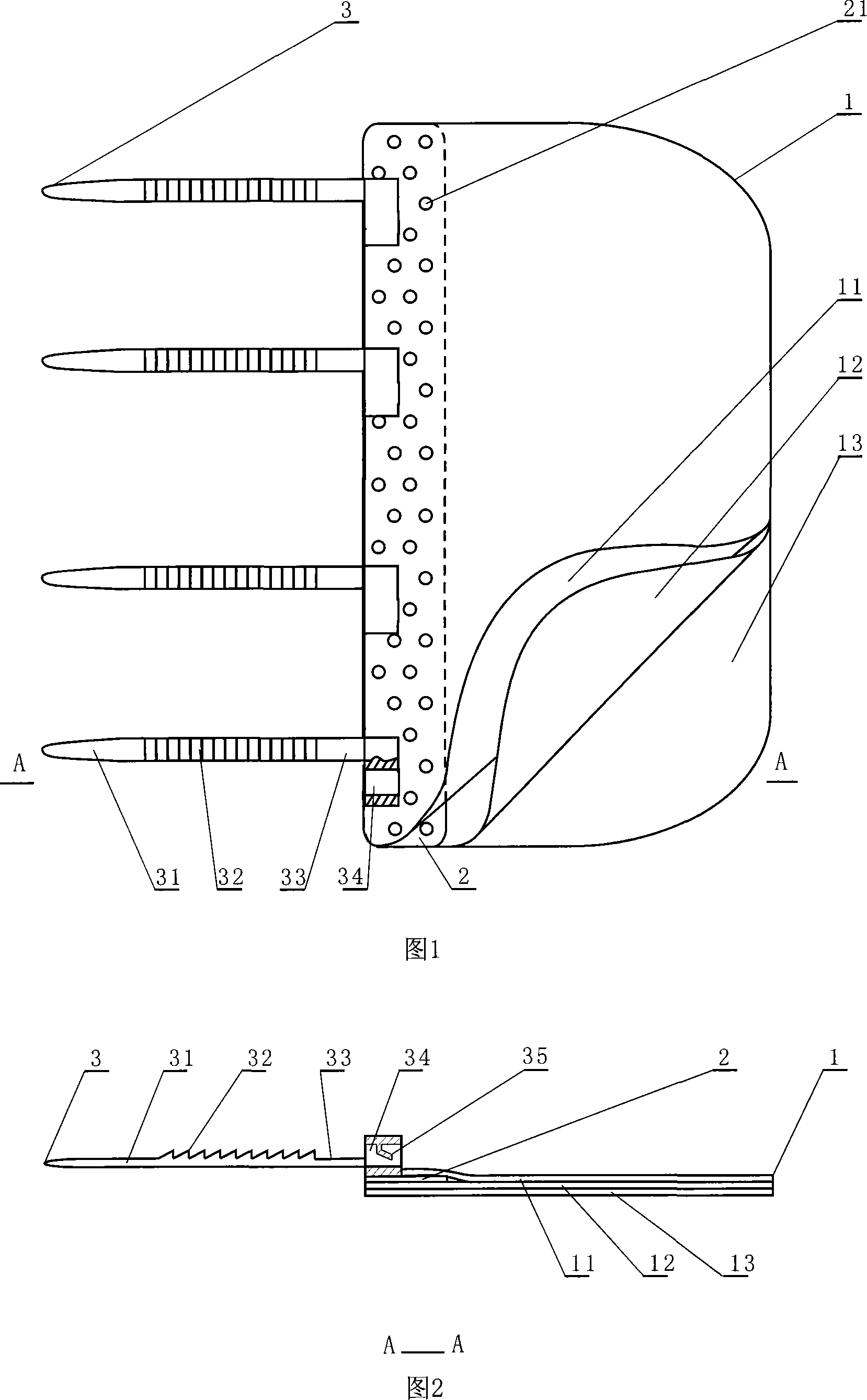
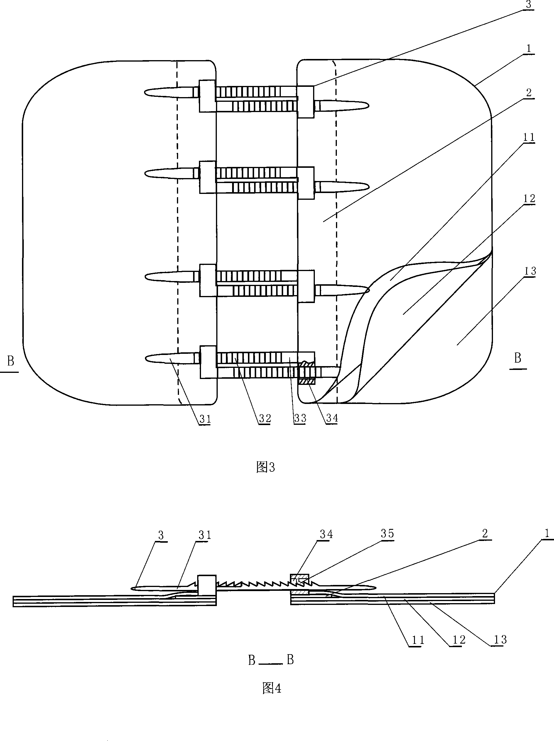
[0014] Referring to Fig. 1 and Fig. 2, the present invention is composed of two substrates, each of which includes a sticker 1, a reinforcing rib 2, and a lock 3, and the sticker 1 is a flat soft body made of a breathable soft material along the One side of its length direction is provided with a reinforcing rib 2, and the sticker 1 is composed of an upper layer of viscose 11, a lower layer of viscose 12, and a protective layer 13; 12, one side is bonded with the protective layer 13, and the other side is fixedly connected with the viscose upper layer 11. The reinforcing rib 2 is provided with a circular, square or diamond-shaped vent hole 21 and several locks 3 are arranged equidistantly; the lock 3 is L-shaped and is composed of a lock bar 31 and a lock seat 34, and the lock bar 31 is provided with a lock The teeth 32 , the gap area 33 , and the lock seat 34 are provided with a lock bolt 35 . The lock tooth 32 is allowed to pass through the corresponding lock seat 34 in one...


PUM


Abstract

The invention discloses a skin wound suturing machine and a suturing method thereof. The suturing machine is formed by two substrates and each substrate of the suturing machine includes a rubberized fabric, a reinforcing rib and lock catches. The rubberized fabric is a ventilating soft material and the reinforcing rib is arranged along the length direction of the rubberized fabric. The rubberized fabric comprises an upper rubberized fabric layer, a lower rubberized fabric layer and a protection layer. The reinforcing rib is arranged between the upper rubberized fabric layer and the lower rubberized fabric layer. The reinforcing rib is provided with a ventilating hole and a plurality of lock catches with same intervals. The lock catch is L-shaped and consists of a locking strip and a lock bracket. The locking strip is provided with a lock gear and a clearance area. The lock bracket is provided with a lock plunger. The two substrates of the invention are connected mutually by penetrating the lock bracket of each other through the locking strip of each own so as to apply a force at two sides of the wound by simultaneously drawing the corresponding locking strip at two sides of the wound when suturing. The invention rotates one of the two substrates by 180 degrees according to a clockwise or anticlockwise direction and the structures of the two substrates are completely consistent and only one substrate is needed manufacturing during production. The invention has the advantages of novel structure, simple operation, convenient use and low manufacture cost.

Description

technical field [0001] The invention relates to the field of medical technology, in particular to a surgical suturing medical device and a suturing method thereof, in particular to a skin wound suturing device and a suturing method thereof. Background technique [0002] In the prior art, after the operation of the patient, the wound is sutured with thread, which not only consumes the energy of the doctor, but also increases the pain of the patient, leaving obvious scars for suturing; the new wireless suture technology has attracted wide attention in the medical field, and the Chinese patent ZL 03117364.0 discloses a "Skin Wound Locker". Its structure is two base belts, on which keyholes are respectively set, and a two-way or one-way ratchet is used to cooperate with the keyhole to lock the wound to achieve the purpose of locking ; The problem with this structure is: for the two-way spine, when pulling one end of the spine, a reaction force needs to be applied to the keyhole ...

Claims


Application Information

Patent Timeline
IPC IPC(8): A61B17/04
Inventor 樊东辉
Owner 江苏泰应生物科技有限公司
Why Eureka
Try Eureka