Ceramics injection moulding automatic molding equipment

An automatic forming and hot die casting technology, applied in the field of ceramic machinery, can solve the problems of insufficient smoothness, incision, continuous operation for a long time, and low efficiency.

Inactive Publication Date: 2008-07-30
魏金富
View PDF1 Cites 30 Cited by
  • Summary
  • Abstract
  • Description
  • Claims
  • Application Information

AI Technical Summary

Problems solved by technology

[0002] Most of the existing industrial ceramic hot die-casting adopts the traditional manual operation mode, that is, the die-casting work on the blank is completed by manually operating the mold. This operation is especially used in the production of lighting and electrical appliances with complex inner cavity structures. Ceramics are very common. Although this model has the characteristics of good demoulding and redundant waste removal, its low efficiency and high labor intensity are the biggest disadvantages. In the current global economic integration and labor tensions Under the current situation, it is very difficult for enterprises to complete large orders in a relatively short period of time. In order to cater to changes in the market situation, improve the production efficiency of enterprises themselves, and seize fleeting business opportunities, many enterprises are planning to develop An automatic molding machine for ceramic hot die casting, but when solving the bottleneck problem of how to effectively remove redundant waste without producing burrs, and how to automatically demould the product, the plan was suspended or another solution was not obtained. open it up
[0003] Of course, there are also more successful technical solutions. ...

Method used


Image

  • Ceramics injection moulding automatic molding equipment
  • Ceramics injection moulding automatic molding equipment
  • Ceramics injection moulding automatic molding equipment

Examples


Embodiment Construction

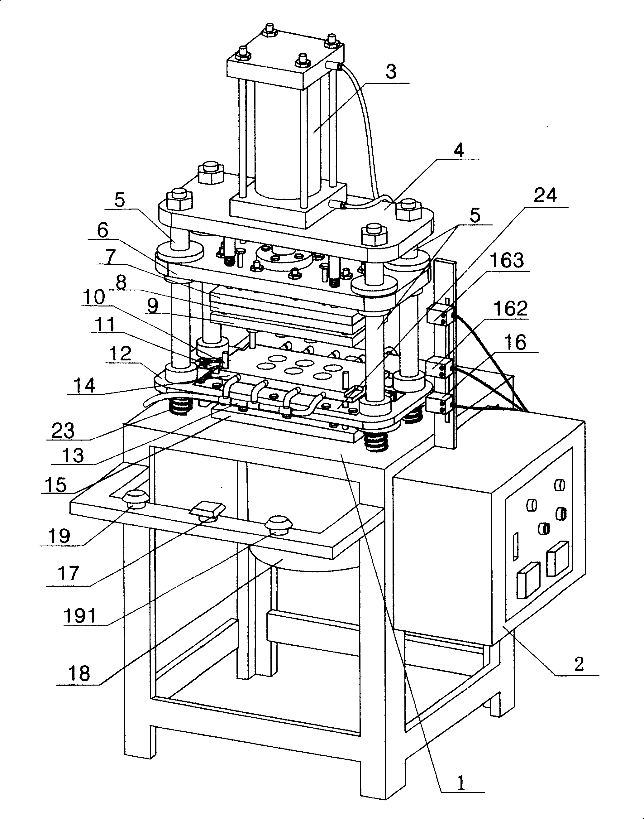
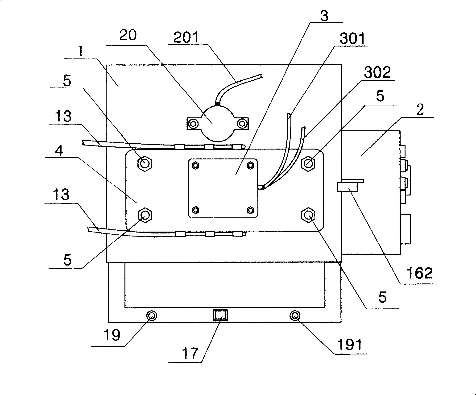
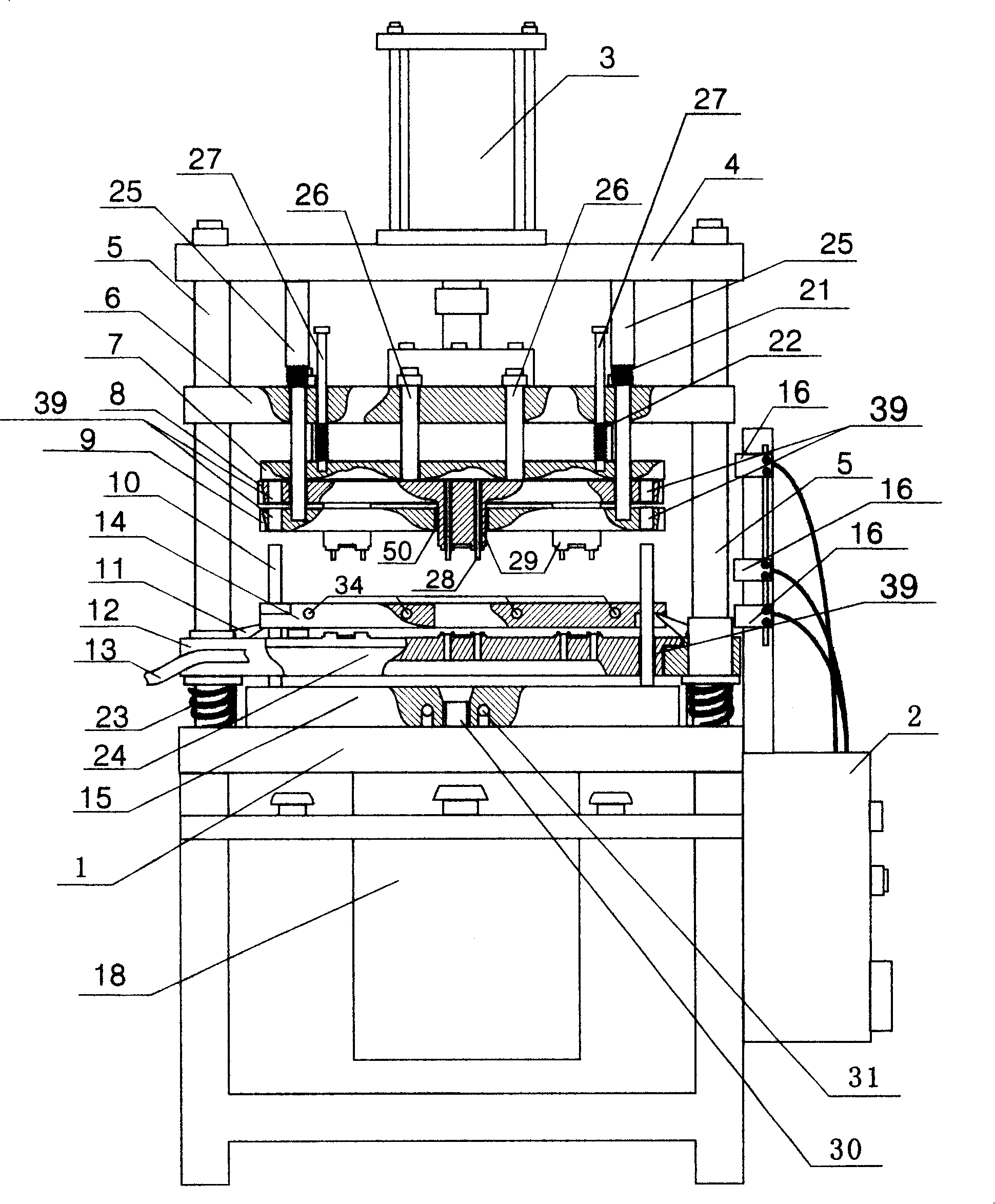
[0027] A ceramic hot die-casting automatic molding device of the present invention will be further described in detail below in conjunction with the accompanying drawings.

[0028] refer to figure 1 , figure 2 , image 3 , figure 1 It is a three-dimensional structure diagram of a ceramic hot die-casting automatic molding device according to the present invention, figure 2 It is a top view of a ceramic hot die-casting automatic molding device according to the present invention, image 3It is a partial cross-sectional view of a ceramic hot die-casting automatic molding device according to the present invention. As shown in these three drawings, four guide posts 5 are connected to the upper surface of the machine base plate 1, and the lower ends of these four guide posts are covered with Die-pushing spring 23, lower guide plate 12, upper guide plate 6 also slide sleeve on these four guide pillars, the top of guide pillar fixes a top plate 4 with screw, and a cylinder 3 is i...


PUM


Abstract

The invention discloses an automatic forming machine with a ceramic hot pressure casting, which includes a machine frame, a control system, a material storing bucket, a material conveying pipe, a constant temperature heating part, a guide pillar, an upper guide plate, a lower guide plate, a die and an air cylinder. The invention is characterized in that the feeding plate is firmly arranged on the bottom plate of a machine station and is sleeved with one end of the material conveying pie with the two ends open; the another end of the material conveying pipe is extended into the material storing bucket arranged below the bottom plate; the die consists of a panel, a frame board, a stripper, a fixed plate and a faller; a cavity arranged above the lower guide plate is used for embedding and wrapping the panel in the die neatly; the lower surface of the panel is provided with a feeding groove; the die prying devices are respectively arranged on the left side and the right side of the bottom plate; a plurality of copper pipes with cooling effect are passed through the frame board; in the device, type needles on the faller are inserted into type holes on the panel to resect waste material.

Description

Technical field: [0001] The invention relates to a ceramic machine, in particular to a hot die-casting automatic molding machine used in the industrial ceramics industry to produce lamp decorations with complex inner cavity structures and ceramics for electrical appliances. technical background: [0002] Most of the existing industrial ceramic hot die-casting adopts the traditional manual operation mode, that is, the die-casting work on the blank is completed by manually operating the mold. This operation is especially used in the production of lighting and electrical appliances with complex inner cavity structures. Ceramics are very common. Although this model has the characteristics of good demoulding and redundant waste removal, its low efficiency and high labor intensity are the biggest disadvantages. In the current global economic integration and labor tensions Under the current situation, it is very difficult for enterprises to complete large orders in a relatively sho...

Claims


Application Information

Patent Timeline
IPC IPC(8): B28B3/02
Inventor 魏金富
Owner 魏金富
Why Eureka
Try Eureka