Cavity formwork component of cast-in-situs concrete hollow slab

A cavity mold and hollow plate technology, which is applied to building components, mold shells/templates/work frames, and on-site preparation of building components, can solve problems such as low production efficiency, increased transportation costs, and mold shell damage.

Inactive Publication Date: 2008-07-30
湖南邱则有专利战略策划有限公司
View PDF2 Cites 0 Cited by
  • Summary
  • Abstract
  • Description
  • Claims
  • Application Information

AI Technical Summary

Problems solved by technology

However, when the formwork components in this floor slab are produced, it is inconvenient to make, the production efficiency is low, and it is not convenient for assembly line production. Especially in the transportation and construction process, the formwork transportation is extremely inconvenient, and the overall formwork components occupy a lot The transportation space wastes a lot o

Method used


Image

  • Cavity formwork component of cast-in-situs concrete hollow slab
  • Cavity formwork component of cast-in-situs concrete hollow slab
  • Cavity formwork component of cast-in-situs concrete hollow slab

Examples


Embodiment Construction

[0081] The present invention will be further described below in conjunction with the accompanying drawings and embodiments.

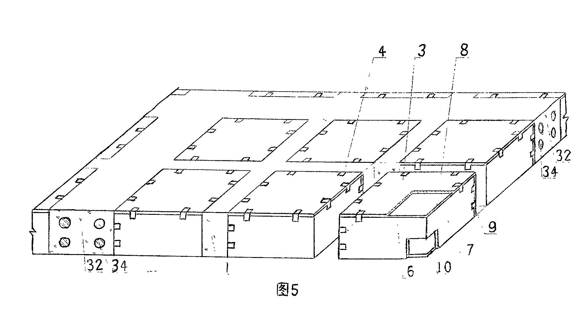
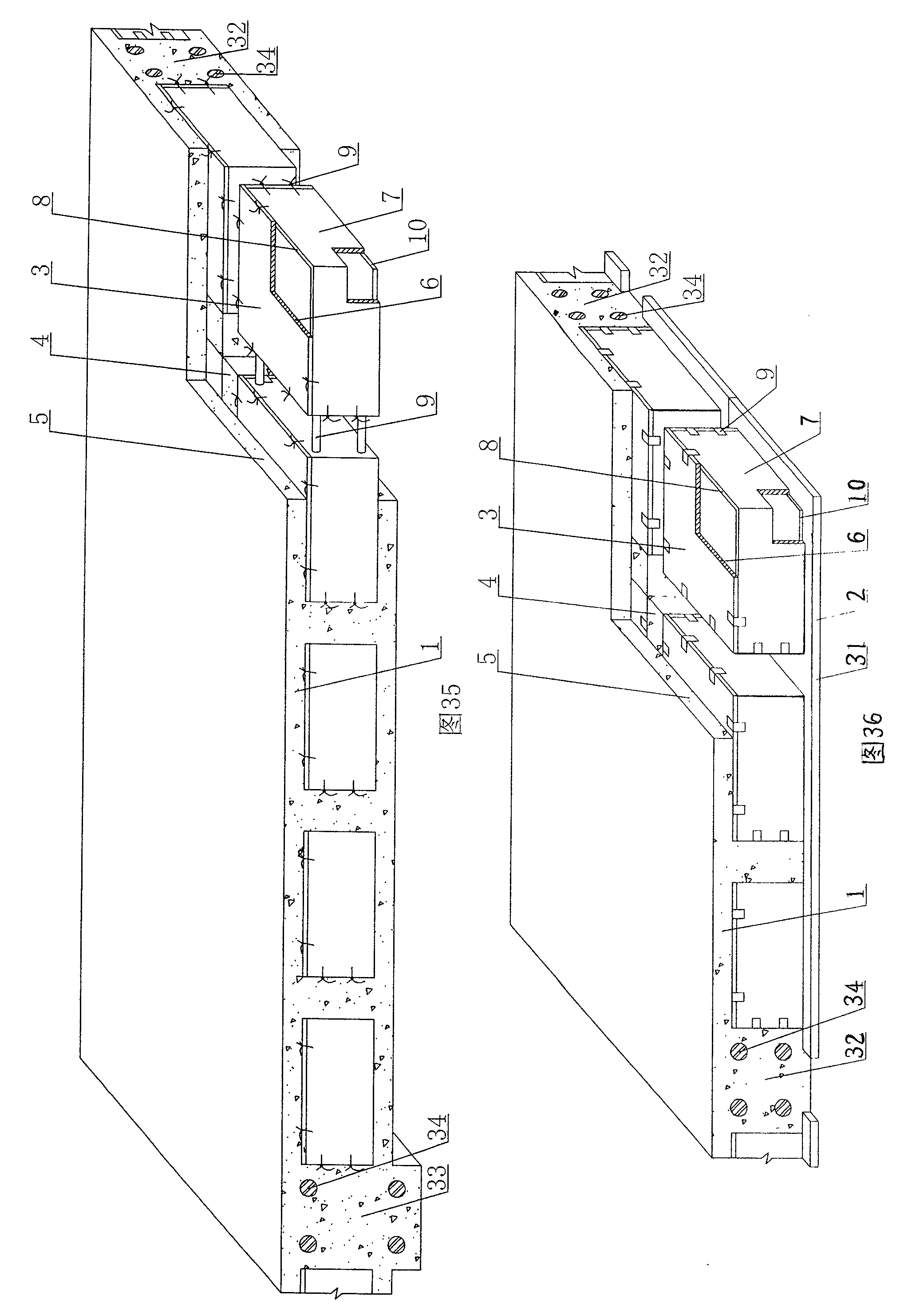
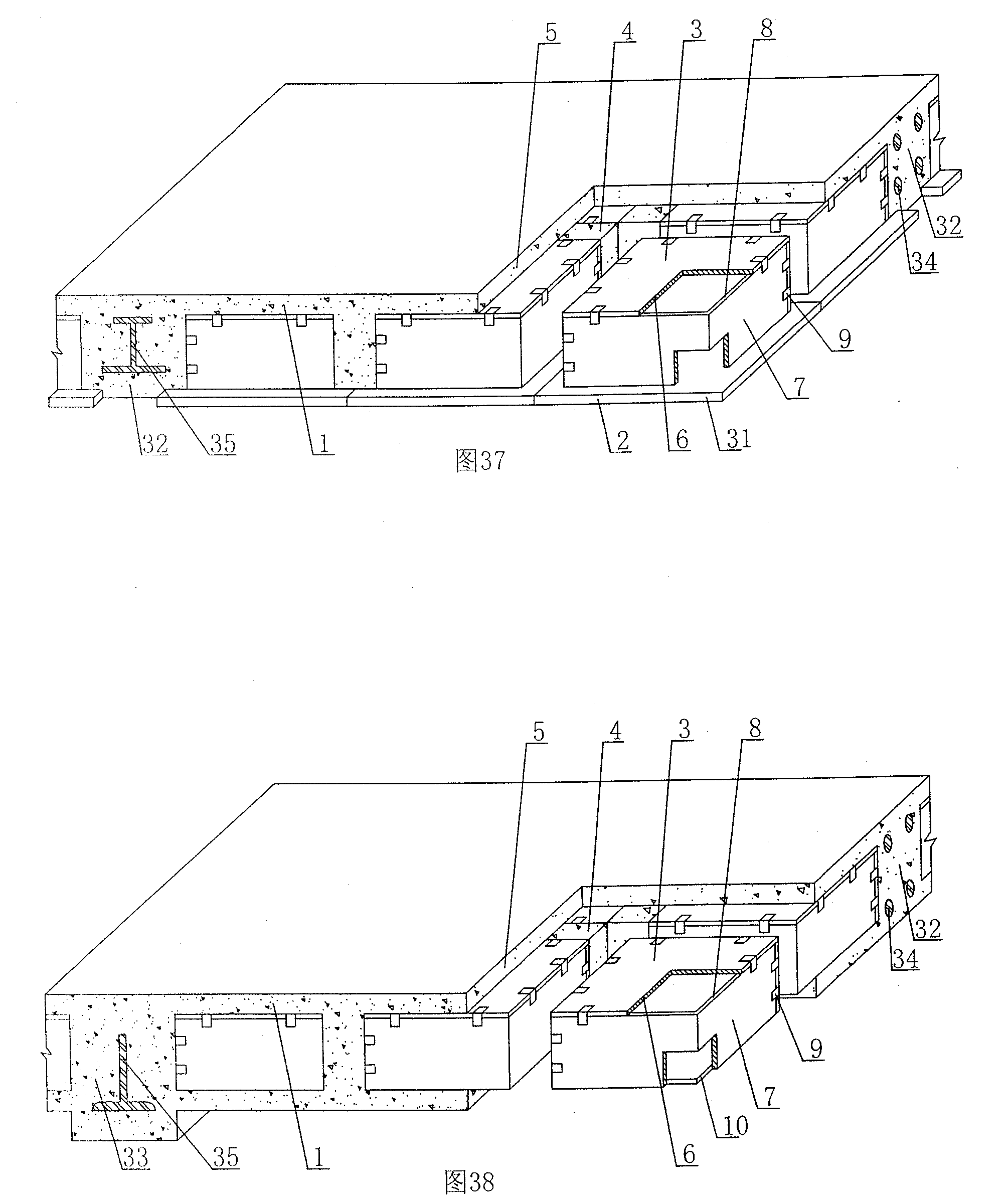
[0082]In the present invention, as shown in the accompanying drawings, the cavity formwork component 3 includes an upper plate 6 and surrounding side walls 7, and the upper plate 6 and the surrounding sidewalls 7 form an open cavity formwork, which is characterized in that the cavity formwork At least two of the components 3 are assembled by prefabricated panels 8, and there are at least two conjoined prefabricated panels in the prefabricated panels 8. The prefabricated panels 8 are assembled into an open cavity or a closed cavity. Connectors 9 are connected as a whole, and at least one prefabricated plate 8 has a female structure 14 on it. In each drawing, 1 is reinforced concrete, 2 is prefabricated thin plate, 3 is cavity formwork member, 4 is cast-in-place reinforced concrete rib, 5 is cast-in-place concrete laminated layer, 6 is upper plate, 7 is s...


PUM


Abstract

The invention relates to a cavity shuttering component used for a cast-in-situ reinforced concrete cored slab, the cavity shuttering component (3) comprises an upper plate (6) and a surrounding side wall (7); wherein, the upper plate (6) and the surrounding side wall (7) form the enclosed cavity shuttering component. The invention is characterized in that the cavity shuttering component (3) consists of at least two precast slabs (8); among the precast slabs (8), at least two precast slabs are siamesed; the precast slabs (8) form an open cavity or an enclosed cavity by splicing; the precast slabs (8) are connected into a whole by a connecting piece (9); at least one of the precast slabs (8) is provided with a female structure (14), therefore, the invention is applicable to cast-in-situ reinforced concrete or a hollow floor system, a roof system, walls and a foundation slab of the prestressed reinforced concrete as well as a vierendeel bridge girder, and is particularly suitable for a hollow flat slab.

Description

[0001] This application is a divisional application of an invention patent application with an application date of June 6, 2005, an application number of 200510075799.1, and a title of "a cast-in-place concrete hollow slab". (1) Technical field [0002] The invention relates to a cavity formwork component for cast-in-place concrete hollow slabs. (2) Background technology [0003] At present, most of the buildings with brick-concrete structure and frame structure use prefabricated hollow-core slabs as floor slabs. This kind of floor slab has the advantages of fast construction speed and low cost, but because there is no firm connection between two adjacent prefabricated hollow-core slabs , Only cement mortar is used to fill the gaps, so not only the integrity is poor, which is not conducive to earthquake resistance, but also cracks and water seepage often occur in the gaps, causing great inconvenience and psychological pressure to the residents. In order to solve the above pr...

Claims


Application Information

Patent Timeline
IPC IPC(8): E04C1/00E04C5/00E04B5/36E04G15/06E04G11/36E04B2/86E02D27/00
Inventor 邱则有
Owner 湖南邱则有专利战略策划有限公司
Why Eureka
Try Eureka