Method for manufacturing rotary compressor

A technology of a rotary compressor and a manufacturing method, which is applied in the direction of rotary piston machines, rotary piston pumps, rotary piston/swing piston pump components, etc., and can solve the problems of low machining accuracy, large gap between blade grooves and blades, Refrigerant leakage and other issues can be improved to improve machining accuracy, suppress gap leakage, and reduce gaps

Inactive Publication Date: 2008-07-30
SANYO ELECTRIC CO LTD
View PDF2 Cites 5 Cited by
  • Summary
  • Abstract
  • Description
  • Claims
  • Application Information

AI Technical Summary

Problems solved by technology

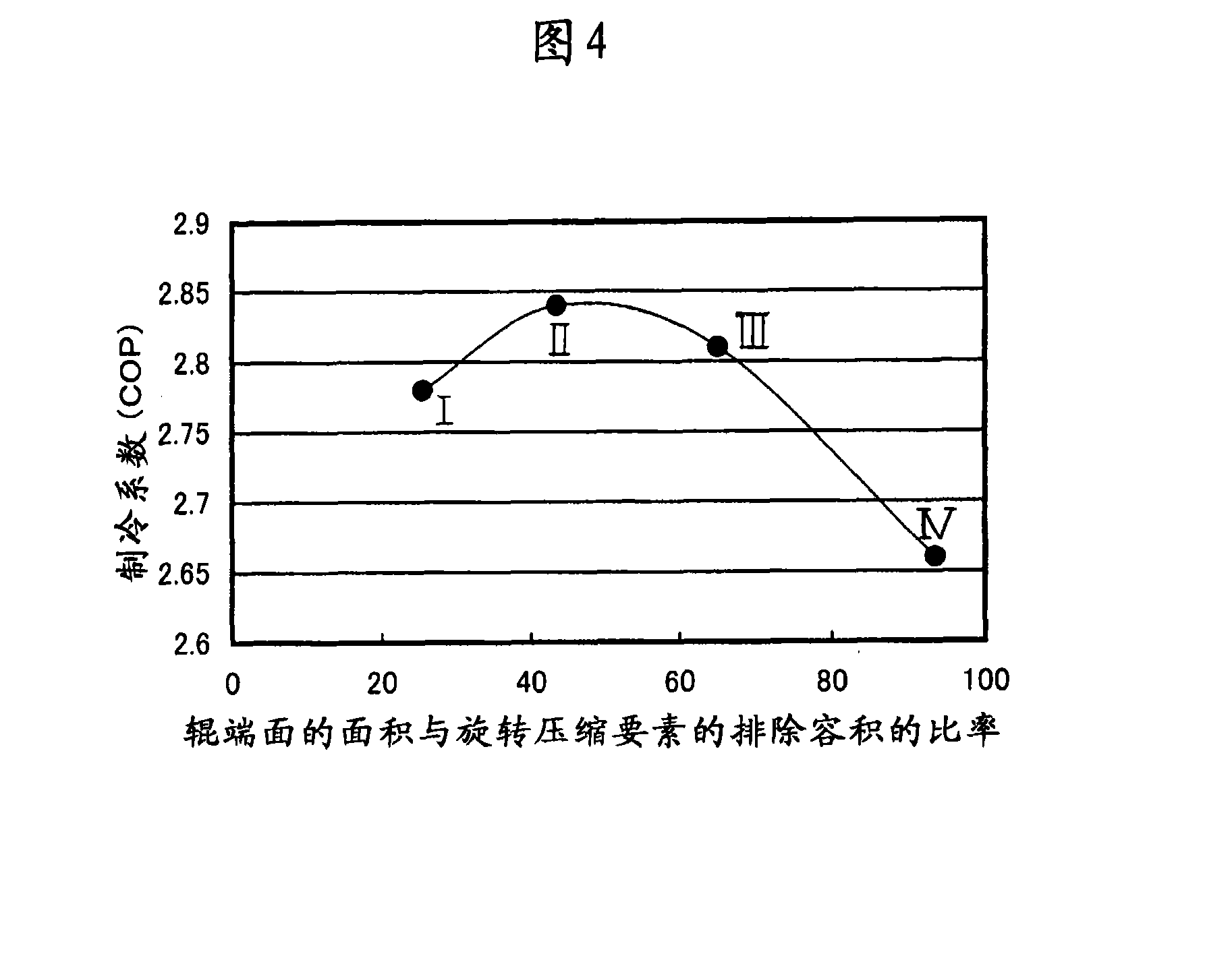
[0005] However, if the end surface area of ​​the roller 148 is too small, the refrigerant leaks from the end surface of the roller 148 because the sealing performance of the end surface of the roller 148 is low.
If the end surface area of ​​the roller 148 is too large, the sliding resistance of the roller 148 increases, and as a result, the input of the rotary compressor 10 increases and the cooling coefficient (Coefficient of Parformance: COP) decreases.
[0006] On the other

Method used


Image

  • Method for manufacturing rotary compressor
  • Method for manufacturing rotary compressor
  • Method for manufacturing rotary compressor

Examples


Embodiment 1

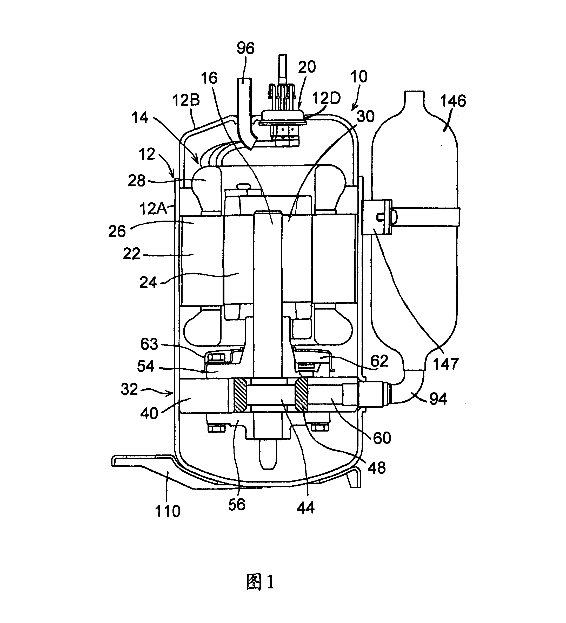
[0023] FIG. 1 is a longitudinal sectional view showing a vertical internal high-pressure single-stage rotary compressor 10 including a rotary compression element 32 as an embodiment of the present invention. In FIG. 1 , a rotary compressor 10 is an internal high-pressure single-stage rotary compressor using fluorine-based refrigerant R410A as a refrigerant. The rotary compressor 10 is composed of a hermetic container 12 as a casing, an electric element 14 as a driving element, and a rotary compression element 32 . The airtight container 12 is constituted by a cylindrical container body 12A made of steel plate and a substantially bowl-shaped end cap (lid body) 12B that closes the upper opening of the container body 12A. The electric element 14 is disposed above the internal space of the container body 12A of the airtight container 12 . The rotary compression element 32 is arranged below the electric element 14 and is driven by the rotation shaft 16 of the electric element 14 ....

Embodiment 2

[0055] In Embodiment 1, the end surface area A of the roller 48 and the rotational compression element 32 are excluded by notching the inner side (the side of the eccentric portion 44 ) of the contact surface of the roller 48 which is in contact with the upper support member 54 and the lower support member 56 . The ratio A / B of volume B is set to 30mm 2 / cm 3 ~60mm 2 / cm 3 , but not limited thereto, it is also possible to change the shape of the eccentric portion 44, or the inner side of the expansion roller 48, to increase the contact area with the upper support member 54 and the lower support member 56, etc., so that the end surface area A of the roller 48 is related to the rotation The ratio A / B of the exclusion volume B of the compression element 32 is set to 30mm 2 / cm 3 ~60mm 2 / cm 3 . Also in this way, the same effect as that of the above-mentioned embodiment can be obtained.

Embodiment 3

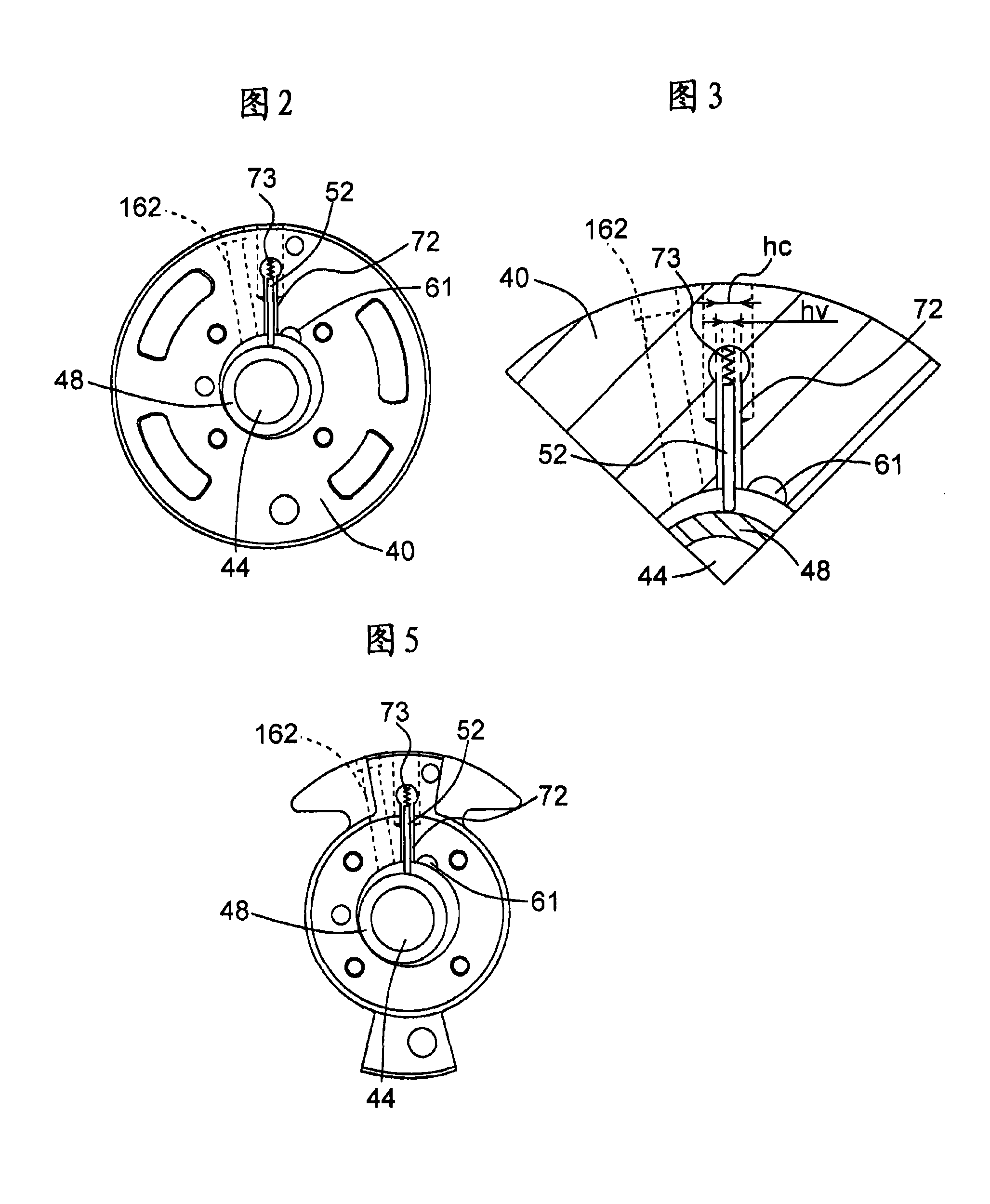
[0057] In Embodiment 1 and Embodiment 2, the cylinder of the rotary compressor 10 adopts the circular cylinder 40 shown in FIG. 2 , but it is not limited thereto. It is also possible to obtain the same effects as those of the above-mentioned respective embodiments.


PUM


Abstract

The invention aims to reduce leakage of a freezing medium and restraining sliding resistance and improving the coefficient of performance (COP) at the same time in a rotary compressor. The rotary compressor (10) of the invention comprises a rotary compression factor (32), a cylinder (40), a roller (48), an upper part support part (54) and a lower part support part (56) of a bearing, wherein, the rotary compression factor is driven by a rotary shaft (16) of a driving factor (14); the rotary compression factor (32) is formed from the cylinder; the roller is arranged in the cylinder (40), and is tabled with an eccentric part (44) of the rotary shaft (16) to eccentrically rotate; the bearing is used for obturating the opening surface of the cylinder (40), and is provided with the rotary shaft (16). The ratio A/B is set at 30mm<2>/cm<3> to 60mm<2>/cm<3>, wherein, A is the contact area of the roller (48) contacting with the upper part support part (54) and the lower part support part (56); B is the removal capacity of the roller (48) and the rotary compression factor (32).

Description

[0001] This application is a divisional application of an invention patent application with the application number 03158147.1, the filing date being September 12, 2003, and the invention title being "rotary compressor and manufacturing method of the rotary compressor". technical field [0002] The present invention relates to a rotary compressor provided with a rotary compression element driven by a rotary shaft of the drive element and a method of manufacturing the same. Background technique [0003] In conventional rotary compressors of this type, refrigerant is sucked into the low-pressure chamber side of the cylinder from the suction port of the rotary compression element, compressed by the action of the rollers and vanes, and then discharged to the outside from the discharge port of the high-pressure chamber side of the cylinder. The roller is installed in the cylinder, fits in the eccentric part of the rotating shaft, and rotates eccentrically in the cylinder. The uppe...

Claims


Application Information

Patent Timeline
IPC IPC(8): F04C18/356F04C29/00
Inventor 原正之坂庭正纯铃木淳一金山孝男
Owner SANYO ELECTRIC CO LTD
Why Eureka
Try Eureka