Thermally robust illuminator probe tip

A probe, heat-resistant technology, applied in the field of lighting probes, can solve problems such as deformation of the end of the lighting probe

Inactive Publication Date: 2008-07-30
ALCON INC
View PDF2 Cites 15 Cited by
  • Summary
  • Abstract
  • Description
  • Claims
  • Application Information

AI Technical Summary

Problems solved by technology

[0017] Embodiments of the present invention provide a new solution to the problem of deformation of the tip of the lighting probe

Method used


Image

  • Thermally robust illuminator probe tip
  • Thermally robust illuminator probe tip
  • Thermally robust illuminator probe tip

Examples


Embodiment Construction

[0032] The drawings illustrate a preferred embodiment of the invention, and like numerals in different drawings represent like and corresponding parts.

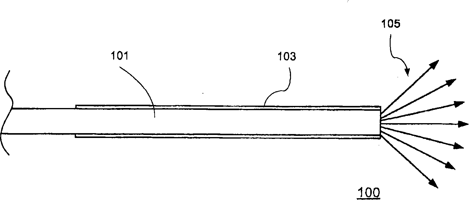
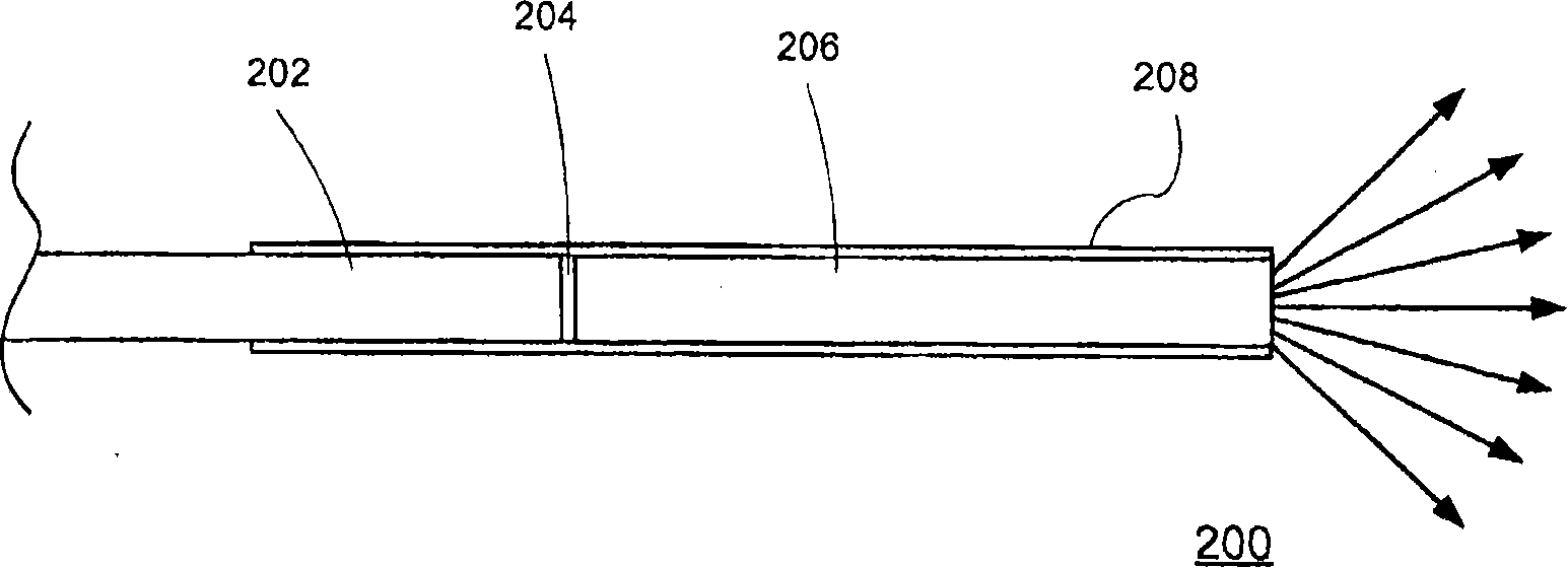
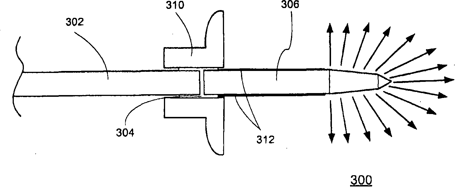
[0033] Various embodiments of the present invention provide illumination probes with heat-resistant terminated plastic optical fibers. The embodiments of the present invention are applicable to plastic optical fibers of all specifications (such as 20, 23, 25, etc.). There is now a trend towards gauge 25 and especially gauge 23 - smaller diameter indications which allow sutureless wounding of the sclera. Heat-resistant lighting probes are part of surgical systems such as ophthalmic lighting and are useful in many medical procedures such as vitreoretinal / posterior segment surgery. A typical ophthalmic illuminator may include a manual component that transmits a relatively incoherent light beam from a light source (eg, xenon light source, halogen light source, etc.) to the surgical field through an optical fiber. The heat resis...


PUM

PropertyMeasurementUnit
refractive indexaaaaaaaaaa

Abstract

In embodiments of the invention, a plastic optical fiber is bonded to a high temperature distal part to form a thermally robust illumination probe. The distal part is short in length, is made of a high temperature material(s), has a proper shape for guiding light in a desired application, and may be coated with a reflective coating to ensure that the light rays trapped within the part do not escape when the side of the part is in contact with high refractive index or absorptive materials. The distal part may be made of high temperature material(s) such as high temperature plastic rods, glass optical fibers, and so on. The distal end may be tapered or sculpted to a desired configuration. The plastic optical fiber and the high temperature distal part may be joined, using an optical adhesive, inside a steel cannula, a plastic hub, an optical connector, etc.

Description

[0001] Cross References to Related Applications [0002] This application claims priority under 35 U.S.C. §119 to U.S. Provisional Patent Application No. 60 / 886,140, ​​filed January 23, 2007, which is hereby incorporated by reference in its entirety. This application is related to and is incorporated by reference into the following co-pending U.S. patent applications: Serial No. 11 / 354,615, filed February 15, 2006, entitled "High Throughput Internally Illuminated Probes," which claims the 2005 Priority to U.S. Provisional Patent Application No. 60 / 653,265, filed February 15; U.S. Patent Application No. 11 / 612,234, filed December 18, 2006, entitled "Illuminated Injection Cannula," which claims December 2005 Priority to U.S. Provisional Patent Application No. 60 / 751,175, filed October 16; and U.S. Patent Application No. 10 / 697,350, filed October 30, 2003, entitled "Surgical Wide Angle Illuminators"; incorporated herein by All of the above. technical field [0003] The applicat...

Claims


Application Information

Patent Timeline
Patent Type & Authority Applications(China)
IPC IPC(8): F21V8/00F21W131/20F21V29/15
CPCG02B6/32G02B6/241A61F9/007G02B6/0008A61B18/00
Inventor R·T·史密斯J·R·奥尔德D·Y·林
Owner ALCON INC
Why Eureka
Try Eureka