Luminescence unit

A light-emitting unit and light-emitting surface technology, which is applied in optics, nonlinear optics, instruments, etc., can solve the problems of general products without structure and inconvenience, and achieve the effects of avoiding excessive temperature, improving heat dissipation efficiency, and extending life

Inactive Publication Date: 2008-07-30
GIO OPTOELECTRONICS CORP
View PDF0 Cites 0 Cited by
  • Summary
  • Abstract
  • Description
  • Claims
  • Application Information

AI Technical Summary

Problems solved by technology

[0007] It can be seen that the above-mentioned existing light-emitting unit obviously still has inconvenience and defects in structure and use, and needs to be further improved urgently.
In order to solve the above-mentioned problems, the relevant manufacturers have tried their best to find a solution, but no suitable design has been developed for a long time, and the general products do not have a suitable structure to solve the above-mentioned problems. This is obviously related. The problem that the industry is eager to solve

Method used


Image

  • Luminescence unit
  • Luminescence unit
  • Luminescence unit

Examples


Embodiment Construction

[0040] In order to further explain the technical means and effects of the present invention to achieve the intended purpose of the invention, the specific implementation, structure, characteristics and effects of the light-emitting unit proposed according to the present invention will be described in detail below in conjunction with the accompanying drawings and preferred embodiments. The description is as follows.

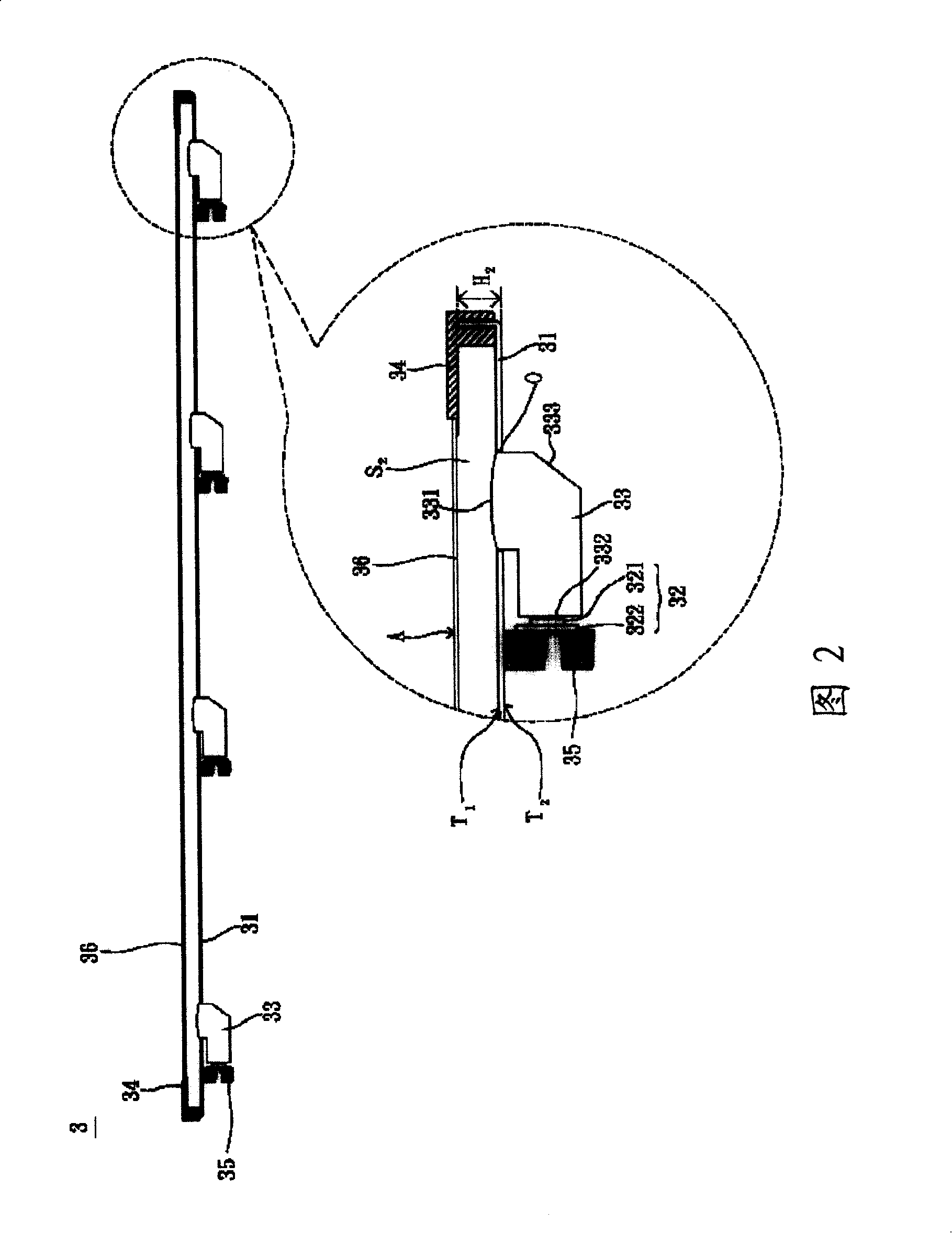
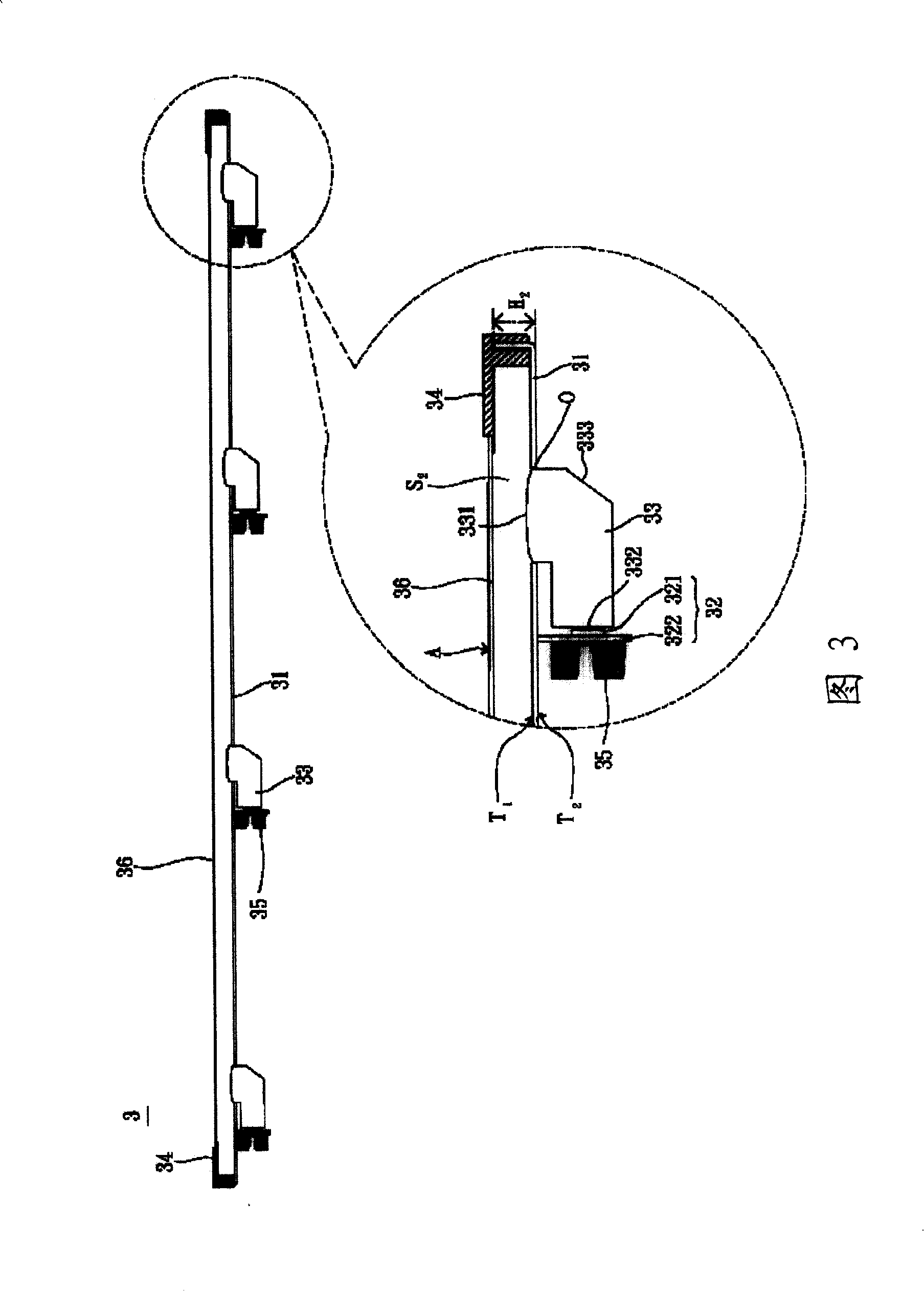
[0041] Please refer to FIG. 2 , the light emitting unit 3 according to a preferred embodiment of the present invention is an example of a backlight module of a liquid crystal display device, and the backlight module is a direct type backlight module. The light emitting unit 3 at least includes a light emitting surface A, a casing 31 , a light emitting diode module 32 and a light guide element 33 .

[0042] The light-emitting surface A refers to a surface on which the light-emitting unit 3 emits light. The shape and structure of this surface can be arranged differe...


PUM


Abstract

The invention relates to a luminescent unit comprising a luminescent plane, a shell, a light emitting diode module and a light-guide element. The shell has an opening and an emergent light side, wherein the opening is substantially parallel to the luminescent plane. The light emitting diode module has at least one light emitting diode and a circuit board eclectically connected with the light emitting diode, wherein the light emitting diode module is positioned at the side opposite to the emergent light side of the shell. One end of the light-guide element is arranged relative to the opening, and the other end thereof is adjacent to the light emitting diode. The invention can increase the service life and the heat-dissipation efficiency of the luminescent unit.

Description

technical field [0001] The invention relates to a light emitting unit, in particular to a light emitting unit using a light emitting diode as a light source. Background technique [0002] With the advancement of technology, people have also developed more diverse light-emitting units. In general, the light-emitting unit can be a lighting device, an outdoor display board, a light source of a projector, or a backlight module of a flat-panel display device. [0003] Please refer to FIG. 1, taking the backlight module as an example of a light-emitting unit, the conventional light-emitting unit 1 at least includes a front frame 11, a back plate 12, a plurality of light-emitting diode modules 13 and an optical film set 14. Wherein, an accommodating space S is formed between the front frame 11 and the back plate 12 1 . The light-emitting diode module 13 is set in the accommodating space S 1 , and each LED module 13 has a plurality of LEDs 131 and a circuit board 132 for drivin...

Claims


Application Information

Patent Timeline
IPC IPC(8): G02F1/13357G02F1/133G03B21/14G03B21/16G09F9/00H05K7/20G02F1/1335
Inventor 谢欣珀
Owner GIO OPTOELECTRONICS CORP
Why Eureka
Try Eureka