Device for detecting large-sized perspective glass primary and secondary mirror spacing

A telescope, primary and secondary mirror technology, used in telescopes, measuring devices, optical devices, etc., can solve the problems of low spatial resolution and high cost of large-diameter optical systems, and achieve the effect of low system cost

Inactive Publication Date: 2008-08-06
INST OF OPTICS & ELECTRONICS - CHINESE ACAD OF SCI
View PDF0 Cites 15 Cited by
  • Summary
  • Abstract
  • Description
  • Claims
  • Application Information

AI Technical Summary

Problems solved by technology

[0003] The detection of adjustment errors of large-apertu...

Method used


Image

  • Device for detecting large-sized perspective glass primary and secondary mirror spacing
  • Device for detecting large-sized perspective glass primary and secondary mirror spacing

Examples


Embodiment Construction

[0028] The present invention will be described in detail below in conjunction with the accompanying drawings and specific embodiments.

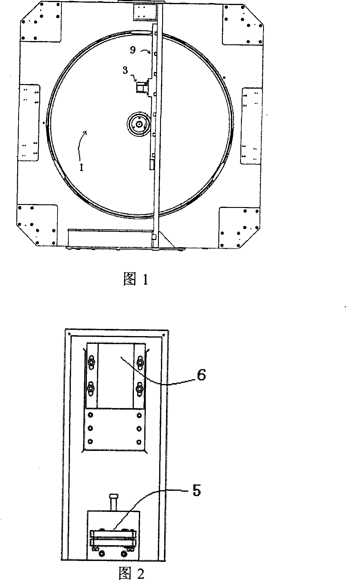
[0029] Fig. 1 shows the position relationship diagram of the guide rail, the pentaprism and the main mirror. The installation direction and the direction of motion of the pentaprism are shown in the figure. Can step translation along guide rail 9 directions, the working surface of guide rail 9 is installed in the direction parallel to the vertical diameter of main mirror 1, and the distance with the vertical diameter of main mirror 1 should make the motion direction and The vertical diameters of the main mirror 1 coincide, and the base of the guide rail 9 is directly connected to the main mirror support (cross).

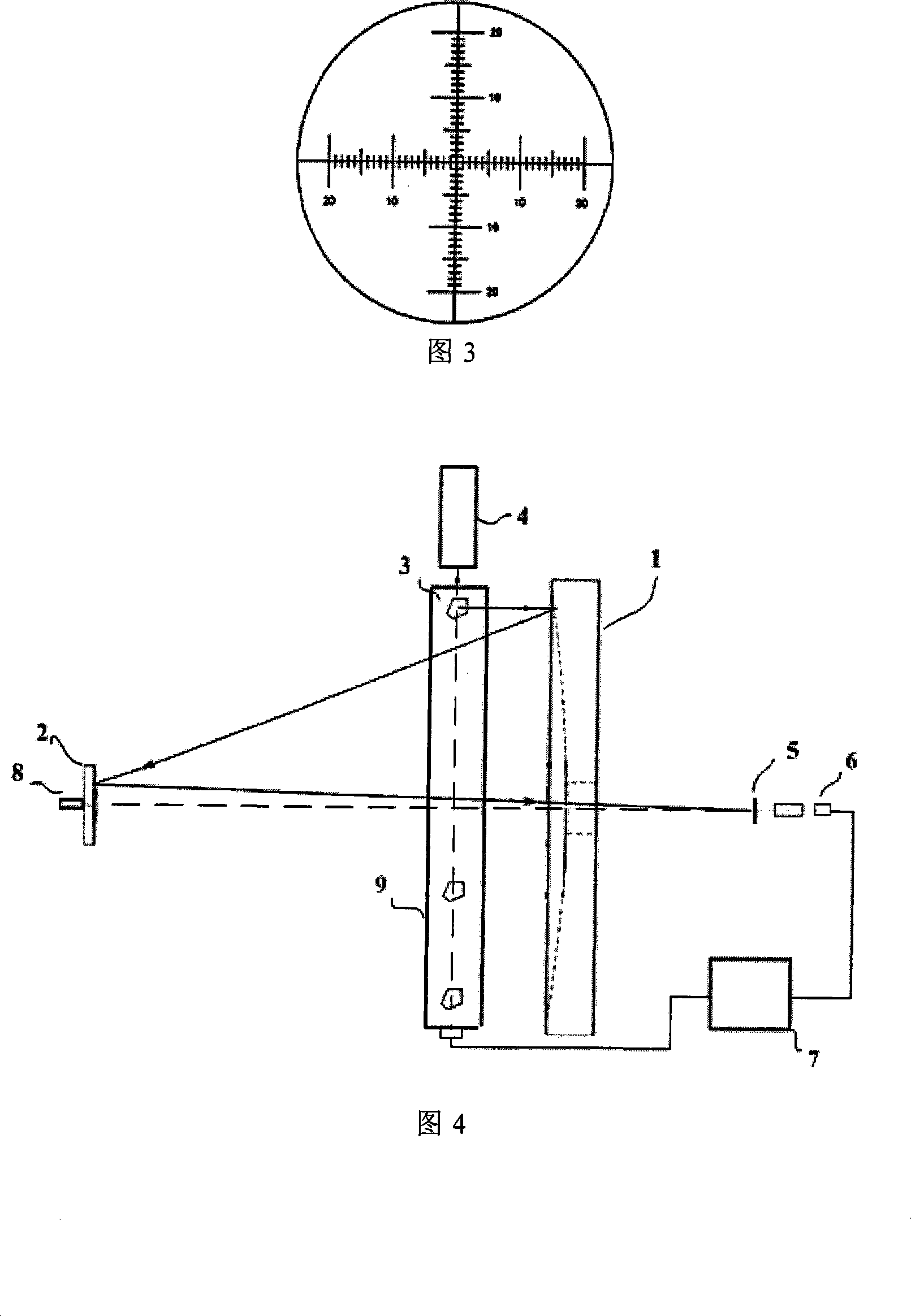
[0030] Figure 2 is a structural diagram of the reticle and CCD detection system. The reticle is located at the Karnofsky focus of the telescope, and the CCD detection system integrates a CCD image detector and a variable magnificati...


PUM


Abstract

An apparatus for detecting spacing between a primary mirror and a secondary mirror, which comprises an auto-collimator, a pentaprism, a guide rail, a reticle, a CCD detection system and a monitoring computer, wherein the guide rail is arranged in parallel direction of vertical diameter of the primary mirror, the pentaprism is arranged at the guide rail and can be translated along the vertical direction, parallel rays emitted from the auto-collimator is turned 90 degrees via the pentaprism and then via telescope optical system to converge at primary optical axis, the reticle is arranged at Cassegrain focus, the CCD detection system is employed for image-forming of the parallel rays convergent point and the reticle, the monitoring computer is capable of calculating the centre of mass of the images detected by CCD detection system and obtaining a group of image points position, while another group of image points position can be obtained by moving the pentaprism, radial scanning of the primary mirror can be achieved by continue moving, and a movement path of the centre of mass of image points can be obtained, thereby spacing error between the primary mirror and the secondary mirror is obtained via processing of the monitoring computer. The apparatus achieves auto-detecting of the spacing between the primary mirror and the secondary mirror of the telescope, increasing the detecting accuracy, thereby providing important guarantee for later system adjusting of large telescope.

Description

technical field [0001] The invention belongs to the detection technology research field in the later stage of telescope development, and relates to a device for detecting the distance between primary and secondary mirrors of a large telescope. Background technique [0002] The light-gathering ability of the telescope increases with the increase of the aperture. The stronger the light-gathering ability of the telescope, the fainter and farther celestial objects can be seen. This is actually the ability to see the earlier universe. The development of astrophysics requires telescopes with larger apertures. However, with the increase of the aperture of the telescope, a series of technical problems follow one after another, one of which is the detection of the adjustment error of the large-aperture optical system. [0003] The detection of alignment errors of large-aperture optical systems is often costly and has low spatial resolution. The scheme of detecting large-aperture le...

Claims


Application Information

Patent Timeline
IPC IPC(8): G01B11/14G02B23/00
Inventor 杨伟吴时彬曹学东景洪伟杨文志
Owner INST OF OPTICS & ELECTRONICS - CHINESE ACAD OF SCI
Why Eureka
Try Eureka