
Omnipotent secure plug with the alarm device

A technology for safety plugs and alarm devices, which is applied to parts of connection devices, coupling devices, measuring devices, etc., can solve problems such as potential safety hazards, unfavorable troubleshooting, and failure of alarms by all-round safety plugs, so as to eliminate hidden dangers of personal safety Effect

Inactive Publication Date: 2008-08-06
钱加灿
View PDF0 Cites 8 Cited by
  • Summary
  • Abstract
  • Description
  • Claims
  • Application Information

AI Technical Summary

Problems solved by technology

[0003] Although the existing all-round safety plug can prevent the danger of electric shock once it leaks, it is still impossible to clearly know whether it is the phase wire, the neutral wire leakage or the ground wire, which is not conducive to troubleshooting and eliminating the potential danger of electric shock. Therefore, in order to improve the safety of all-round The safety of the plug not only requires that the circuit can be cut off in time when the ground wire is live, but also a live wire alarm device must be installed to warn the user that the ground wire has leaked, so as to eliminate this potential danger in time and ensure safe use.
However, the existing all-round safety plug does not have an alarm device
[0004] In addition, the existing all-round safety plug cannot alarm when the phase line and the neutral line are reversed, and there are potential safety hazards

Method used


Image

  • Omnipotent secure plug with the alarm device
  • Omnipotent secure plug with the alarm device

Examples


Embodiment Construction

[0015] The present invention will be further described in detail below in conjunction with the accompanying drawings and embodiments.

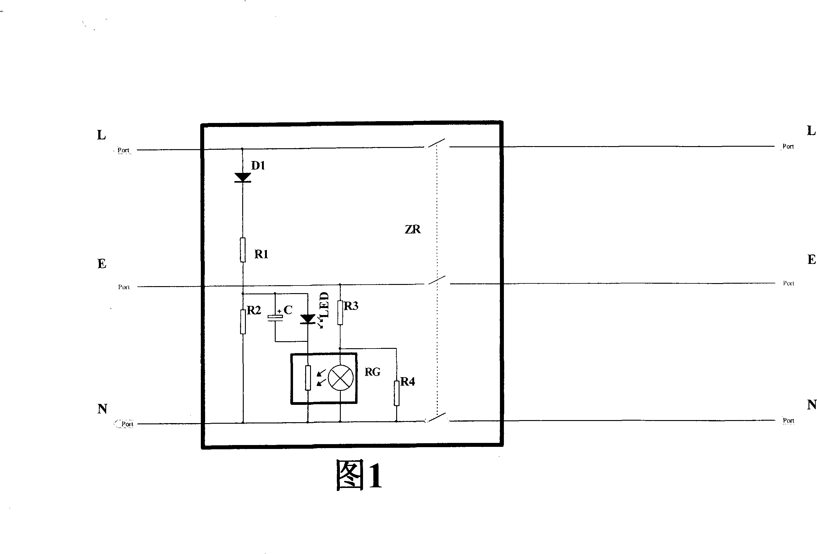
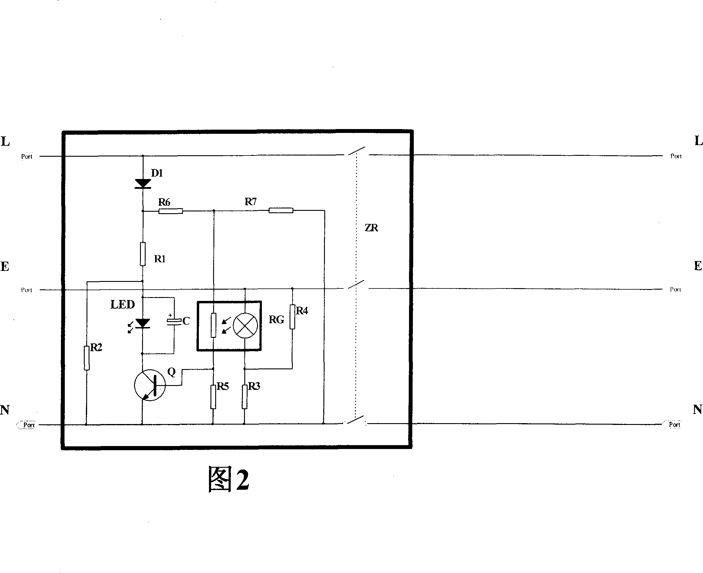
[0016] As shown in Figure 1, RG in the figure is an optocoupler. The optocoupler is composed of a dark box, a neon lamp and a photosensitive resistor. The neon lamp and the photosensitive resistor are placed in the dark box, and a small hole is opened on the dark box. LED is a flash tube, D1 is a rectifier diode, R1, R2, R3, R4 are resistors, and C is an electrolytic capacitor.

[0017] An all-round safety plug with an alarm device, including ground, zero, and phase three-wire connections with switches. The flash alarm circuit is connected in series with the photoresistor in the optocoupler RG and connected to the input pins of the phase line L and the neutral line N. Between the terminals, the two ends of the neon lamp are connected in parallel with the resistor R4, and then connected in series with the resistor R3, and the two ends connected...


PUM


Abstract

An omnipotent safety plug with an alarm device comprises a connecting wire for a ground wire, a zero line and a phase line respectively having a switch, as well as a leakage protector consisting of a zero sequence mutual inductor, a release, an amplifier, a rectifier, a test circuit and a silicon controlled rectifier. The present invention also comprises an optical coupler and a sound and / or flash alarm circuit; the optical coupler consists of a dark box, a neon lamp and a photosensitive element; the neon lamp and the photosensitive element are arranged in the dark box; a small hole is arranged on the dark box; the sound and / or flash alarm circuit is connected with one end of the photosensitive element in the optical coupler and then is connected to a position between input pin ends of the phase line and the zero line; the neon lamp is serially connected with a resistor and then is connected with a position between input pin ends of the ground wire and the zero line. The omnipotent safety plug has the advantages that: firstly, when the ground wire is electrified, the plug intensely warns users of the electrified ground wire and ensures that users can concentrate on the potential safety trouble of the electrified ground wire and exclude in time, so as to eliminate personnel safety hidden trouble; secondly, when the ground wire is normally grounded, if the phase line and the zero line are reversely connected, the neon lamp is turned on to flash for warning because high voltage exists between the zero line and the ground wire.

Description

technical field [0001] The invention relates to an all-round safety plug with an alarm device. Background technique [0002] Almighty safety plugs generally include phase, zero, and ground poles with switches, zero-sequence current transformers between the phase and zero lines, test circuits, amplifier circuits, rectifiers, thyristors, releases, and ground wires. It is connected by a moving reed and a static contact, and a zero-sequence current transformer is passed through the ground wire. In addition to detecting whether there is a residual current between the load phase and the neutral wire, it also detects whether the current flows through the ground wire. When there is residual current between the phase line and the neutral line or the ground line has current, the two detection coils will output an induced voltage and amplified by the amplifier to make the release immediately disconnect all the phase, zero or ground lines, that is, cut off the power supply, thereby Eff...

Claims


Application Information

Patent Timeline
IPC IPC(8): H01R13/66H01R13/70H01R13/717G08B7/06G01R19/155H02H3/32
Inventor 钱加灿
Owner 钱加灿
Learn More