Scanner device for interference type image-forming microwave radiometer

A microwave radiometer and scanning device technology, applied in directions such as electromagnetic field characteristics, can solve problems such as complex antenna arrays, and achieve the effects of reducing complexity, improving accuracy and stability, and reducing costs

Inactive Publication Date: 2008-08-13
CENT FOR SPACE SCI & APPLIED RES
View PDF1 Cites 17 Cited by
  • Summary
  • Abstract
  • Description
  • Claims
  • Application Information

AI Technical Summary

Problems solved by technology

[0008] The purpose of the present invention is to solve the problem that the antenna array of the existing imaging system is too complicated, and to provide a new type of high-efficiency scanning device for the interferometric imaging microwave radiometer

Method used


Image

  • Scanner device for interference type image-forming microwave radiometer
  • Scanner device for interference type image-forming microwave radiometer
  • Scanner device for interference type image-forming microwave radiometer

Examples


Embodiment 1

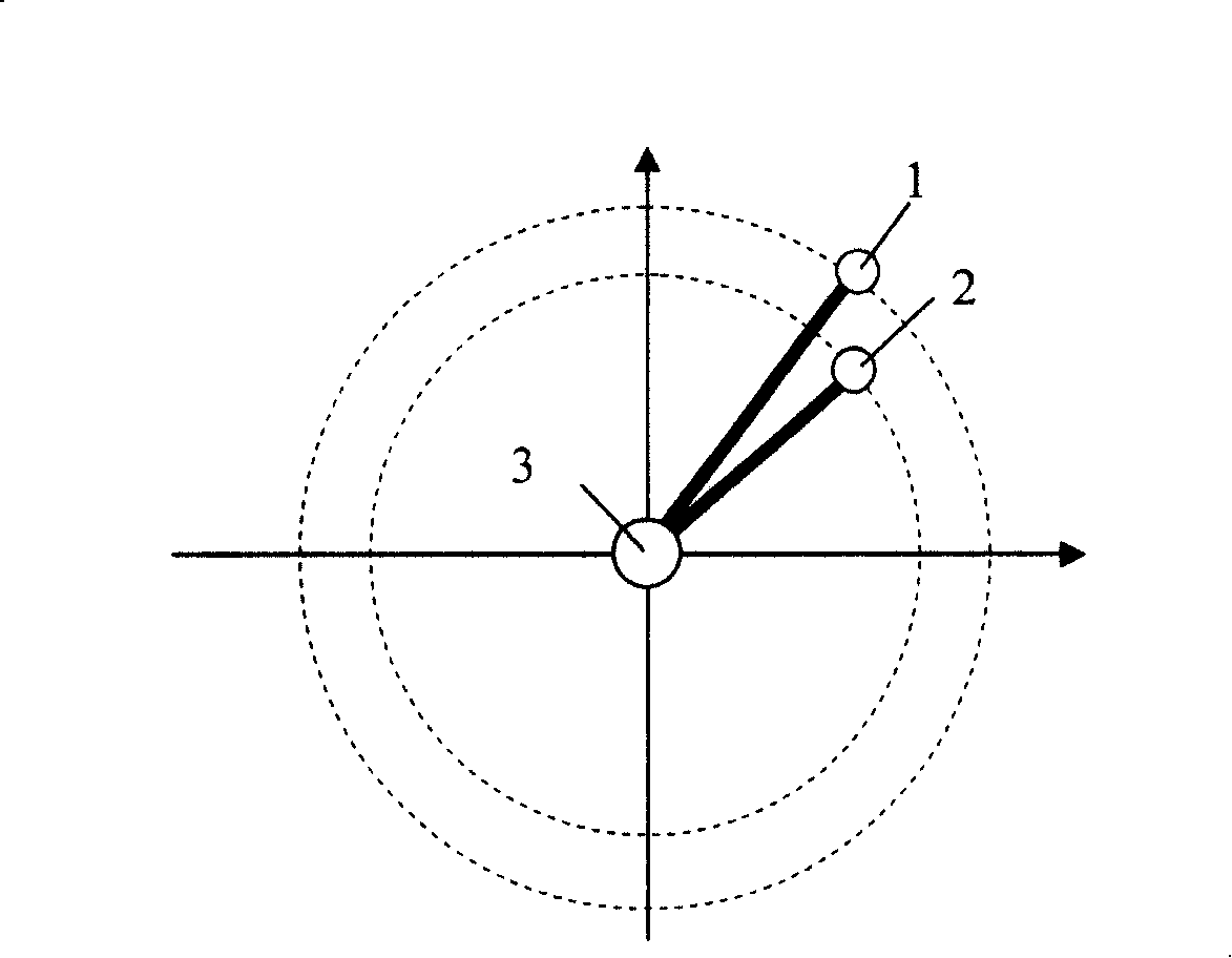
[0041] This embodiment describes a scanning device for an interferometric imaging microwave radiometer suitable for land-based applications. Such as figure 1 As shown, at least two antenna units such as the first antenna unit 1 and the second antenna unit 2 are respectively connected to the rotating device (or called the rotating mechanism) 3 through the connecting device, so that the two antenna units can be coaxially in the same plane Spins independently. Here the distance from the phase center of the first antenna unit 1 to the rotating device 3 or the common rotating shaft is the first distance, and the phase center of the second antenna unit 2 to the rotating device 3 or the distance to the common rotating shaft is the second distance, The two distances are different, for example, the first distance is greater than the second distance. For ease of understanding, the antenna unit with the first distance or the antenna unit and its connecting device to the rotating device...

Embodiment 2

[0056]Based on Embodiment 1, this embodiment describes a scanning device for an interferometric imaging microwave radiometer suitable for spaceborne applications. Since spaceborne applications have high requirements on the stability of satellite attitude, in order to realize the rotation balance of the system and improve the time resolution of the system, the antenna structure of the scanning device adopts a symmetrical multi-pointer distribution method, that is, four "minute hands" - four The "second hand" antenna structure, the "minute hand" and the "second hand" are respectively symmetrical along the central axis of rotation. Such as Figure 7 As shown, a total of 8 antenna units 10 are located at the top of each connecting mechanism, and the antenna units are connected to the central rotating shaft through a rigid extension rod 11 . All the antenna units are distributed symmetrically about the central rotating shaft 18, and rotate around the central rotating shaft in the ...


PUM


Abstract

The present invention discloses a scanning device for interferometric imaging microwave radiometer, which comprises of scanning equipment for interferometric imaging microwave radiometer, rotating device, and at least two antenna units connected through connected device and rotating device respectively to rotate antenna units in one plane coaxially, the distances from phase centre to rotate axel of said at least two antenna units are respectively called the first distance and the second distance which is shorten than the first distance. The present invention reduces the complexity of observation system and cost, improving the precision and stability of system.

Description

technical field [0001] The invention relates to an interferometric imaging microwave radiometer, in particular to a scanning device for the interferometric imaging microwave radiometer. The device can be used not only in land-based imaging systems, but also in airborne and space-borne imaging systems. Background technique [0002] Microwave radiometer is the most basic sensor in the field of passive microwave remote sensing, and it is a high-sensitivity receiver used to measure electromagnetic waves radiated by objects themselves. Due to the strong penetrability of microwaves, the microwave radiometer has the characteristics of all-day and all-weather work, which is unmatched by visible light and infrared sensors. At the same time, because the radiometer itself does not emit electromagnetic signals and has no electromagnetic pollution, it is suitable for Because of the hidden work, and the thermal radiation and electromagnetic scattering of the target itself is an opposite p...

Claims


Application Information

Patent Timeline
Patent Type & Authority Applications(China)
IPC IPC(8): G01R29/08
Inventor 吴季张成刘浩
Owner CENT FOR SPACE SCI & APPLIED RES
Why Eureka
Try Eureka