Prefabricated slab for lamination

A technology of prefabricated slabs and bottom plates, which is applied to floors, building components, buildings, etc., can solve the problems of self-heavy, unadjustable spacing, and high material consumption.

Inactive Publication Date: 2008-08-20
邱则有
View PDF1 Cites 2 Cited by
  • Summary
  • Abstract
  • Description
  • Claims
  • Application Information

AI Technical Summary

Problems solved by technology

", in this utility model patent scheme, the floor slab is composed of multiple reinforced concrete prefabricated components, and the two-way structure is formed by forming a criss-cross layout with existing steel bars and reinforced concrete prefabricated components, without the need for on-site formwork. The existing steel bars and the original steel bars of the reinforced concrete prefabricated components form a criss-cross layout, which can bear two-way loads. However, the assembled floor itself is heavy, and the construction application is extremely inconvenient. The horizontal load-bearing steel bars ...

Method used


Image

  • Prefabricated slab for lamination
  • Prefabricated slab for lamination
  • Prefabricated slab for lamination

Examples


Embodiment Construction

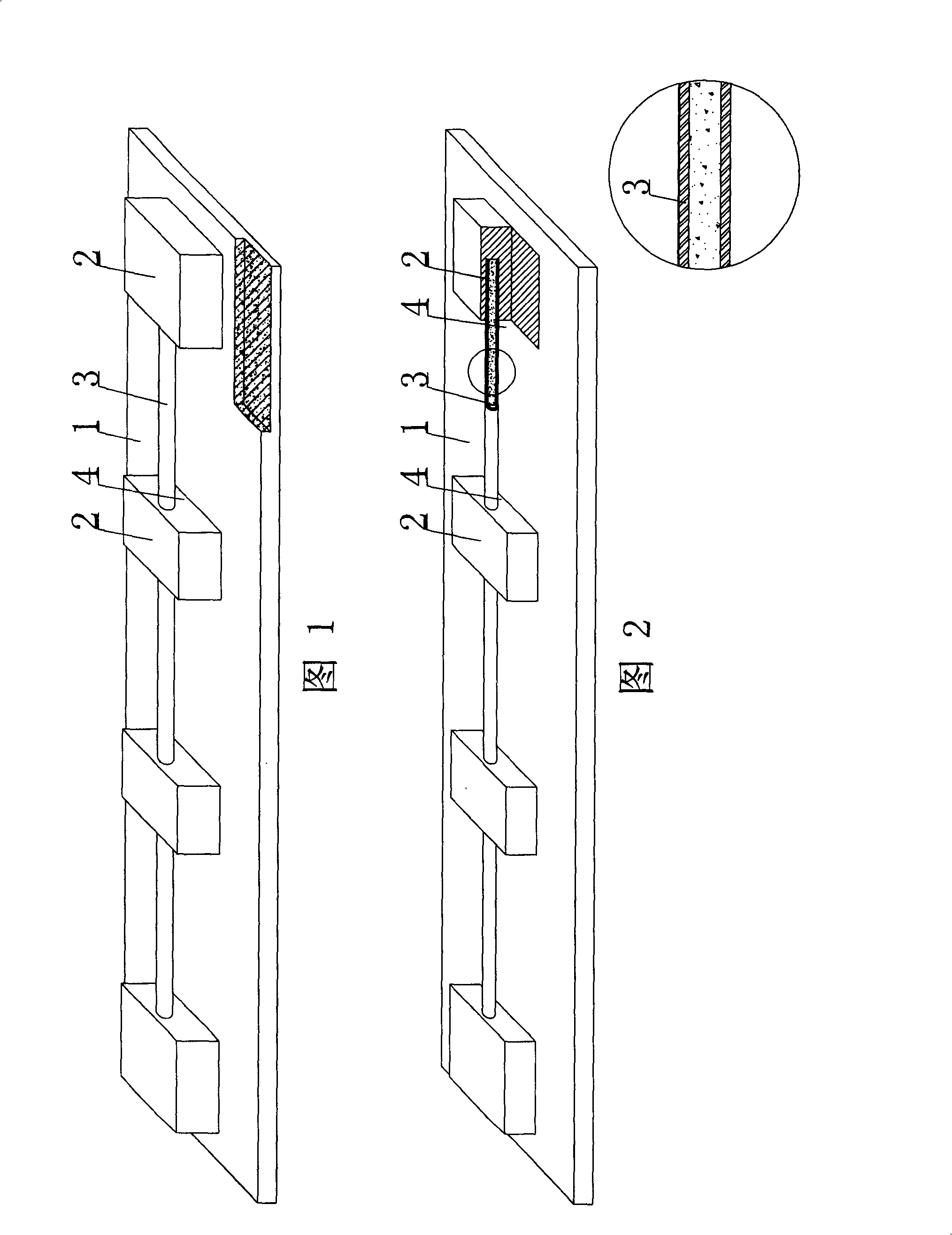
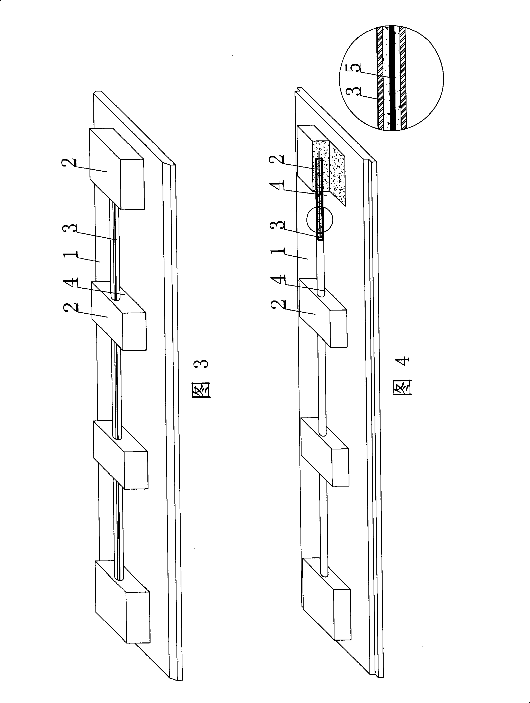
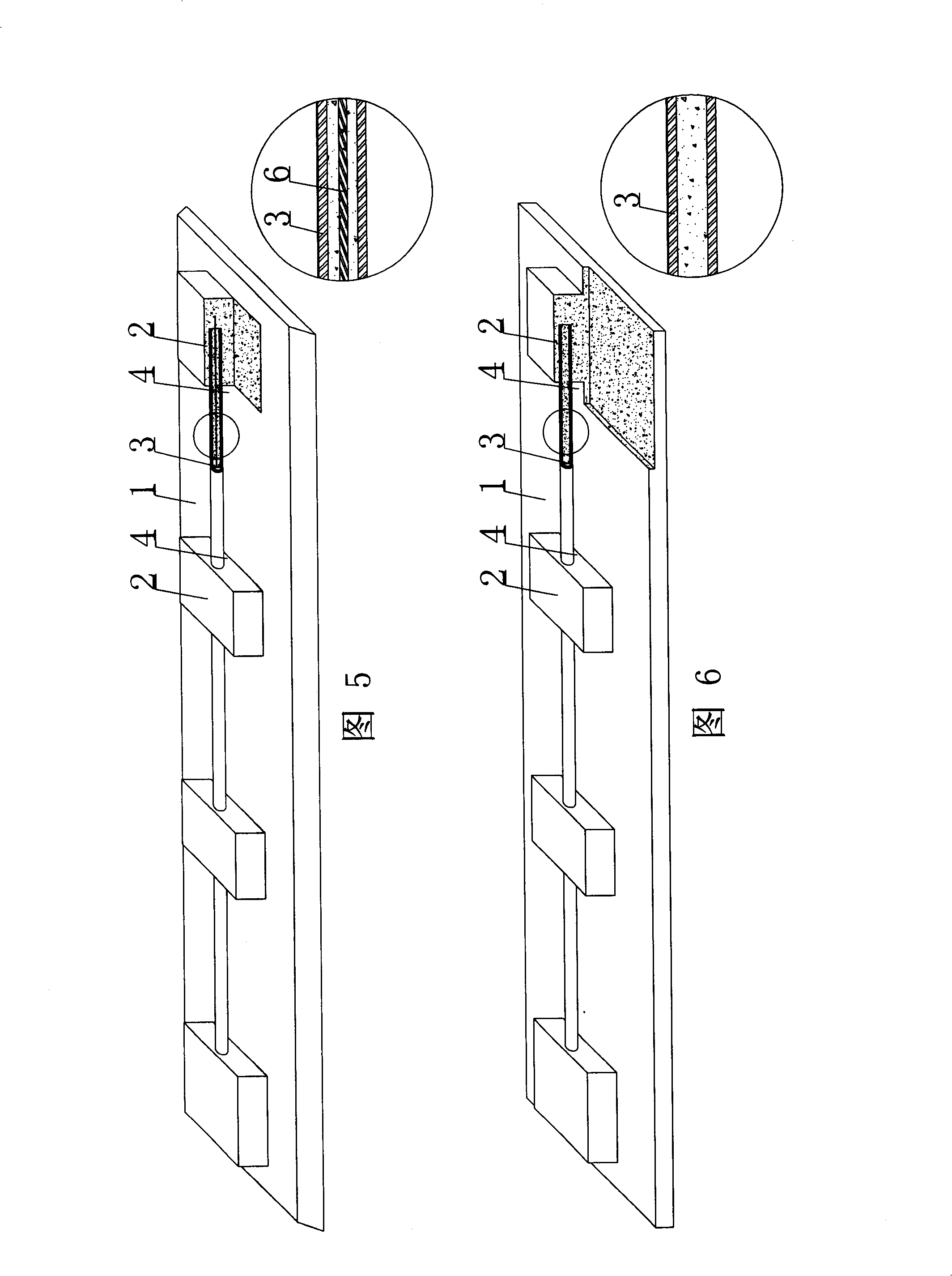
[0098] The present invention will be further described below in conjunction with the accompanying drawings and embodiments.

[0099] As shown in the accompanying drawings, the present invention includes a bottom plate 1, which is characterized in that at least two uprights 2 and at least one bar 3 are arranged on the bottom plate 1, and the bar 3 is arranged transversely on the bottom plate 1, and the bar 3 There is a space distance 4 between the base plates 1, and the rods 3 are laterally connected to support at least two uprights 2. The rods 3, the uprights 2 and the base 1 together form a prefabricated panel for superimposition, and the base 1 is a reinforced concrete base. In each accompanying drawing, 1 is a base plate, 2 is an upright pier, 3 is a rod, and 4 is a space distance. In the following accompanying drawings, those with the same number have the same description. As shown in Figure 1, the prefabricated slab for stacking includes a base plate 1, on which the base ...


PUM

PropertyMeasurementUnit
Lengthaaaaaaaaaa

Abstract

A precast slab used for superposing includes a base plate (1) and is characterized in that the base plate (1) is provided with at least two vertical piers (2) and at least one member bar (3),the member bar (3) is transversely arranged on the base plate (1), a spacing (4) left between the member bar (3) and the base plate (1); the member bar (3) is transversely connected to support at least two vertical piers (2); the member bar (3), the vertical piers (2) and the base plate (1) form the precast slab used for superposing together, and the base plate (1) is a reinforce concrete base plate. The precast slab is suitable for the construction of various cast-in-situ floor system, roof systems, wall bodies, foundation mats and road and bridge projects, especially suitable for a hollow girderless floor system.

Description

(1) Technical field [0001] The invention relates to a prefabricated panel for lamination. (2) Background technology [0002] At present, the floors and roofs of multi-high-rise buildings are mainly cast-in-place concrete as a whole. The general construction method is to set up temporary scaffolding at the construction site, set up formwork, and configure steel bars according to needs, and then carry out concrete construction on site. pouring. Instead of the formwork used on site, the so-called prefabricated formwork is manufactured in the factory in advance, and then the prefabricated formwork is moved into the site and installed on the corresponding scaffolding for construction. Due to its advanced workability, the construction period can be shortened, so It has been widely used in recent years. Such prefabricated formwork includes profiled steel plate, concrete formwork and prestressed concrete formwork, etc. However, this type of prefabricated formwork also has some pro...

Claims


Application Information

Patent Timeline
IPC IPC(8): E04B5/38E04B5/16E04B5/17E04B5/23E04C2/30
Inventor 邱则有
Owner 邱则有
Why Eureka
Try Eureka