Additional elevator gallery bridge assembly and installing method thereof

A technology of covered bridges and components, applied in elevators, transportation and packaging, building maintenance and other directions in buildings, can solve the problems of waste materials, low work efficiency, long construction period, etc., to facilitate production and transportation, reduce adverse effects, improve The effect of construction efficiency

Pending Publication Date: 2019-12-31
JIANGSU RUIYONG CONSTR ENG TECH
View PDF0 Cites 0 Cited by
  • Summary
  • Abstract
  • Description
  • Claims
  • Application Information

AI Technical Summary

Problems solved by technology

Building an additional elevator shaft frame and corridor next to the existing building, such as using the traditional construction method of cast-in-place concrete or welded steel structure, not only has problems such as long construction period, low work efficiency, fire hazard, environmental pollution, waste of materials, etc. And it is easy to interfere with the use of existing buildings, and cause many conflicts with building residents
At present, the elevator shaft has been basically prefabricated, but the bridge slab for walking between the shaft and the building still adopts cast-in-place technology, and its two ends are fixed with the building and the elevator shaft, which makes the uneven settlement of the shaft , unfavorable factors such as wind load are transmitted to the existing building structure through the corridor bridge slabs fixed at both ends, which may have many unsafe effects on the building structure. Therefore, it is necessary to design an elevator that can reduce the impact on the building structure Attached load, fast construction, easy on-site management, and high assembly rate are added to the elevator corridor bridge plate to meet the needs of the market

Method used


Image

  • Additional elevator gallery bridge assembly and installing method thereof
  • Additional elevator gallery bridge assembly and installing method thereof
  • Additional elevator gallery bridge assembly and installing method thereof

Examples


Embodiment Construction

[0038] The present invention will be further described below in conjunction with the accompanying drawings and embodiments.

[0039] like Figure 1 to Figure 5 shown.

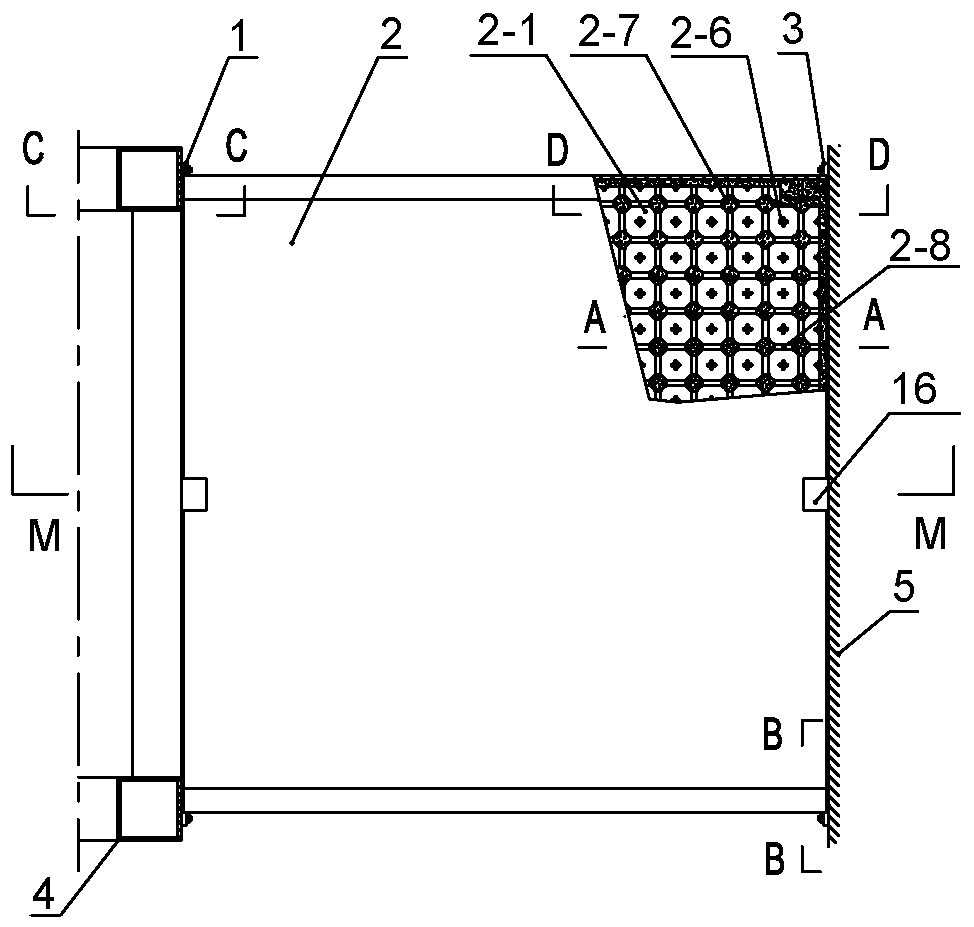
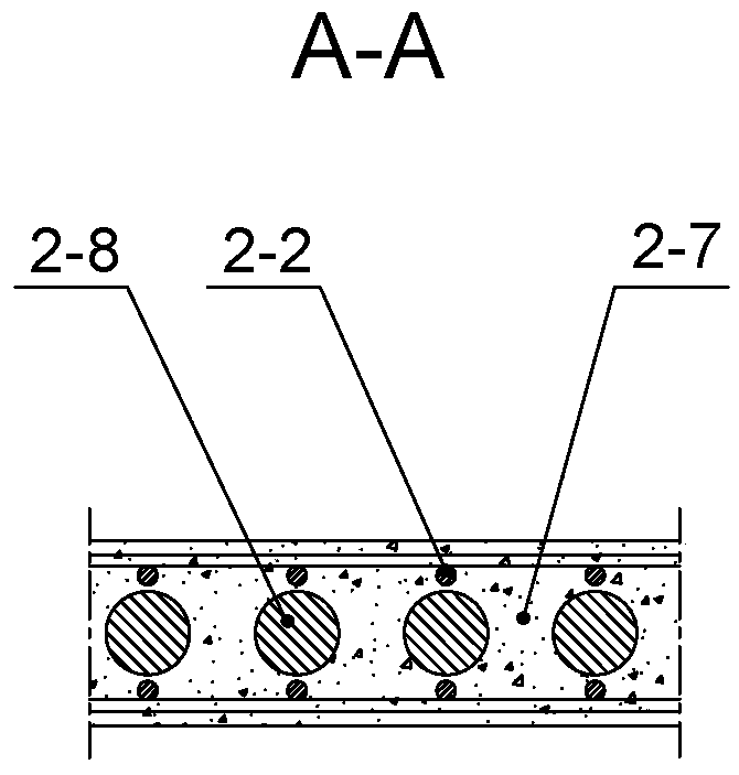
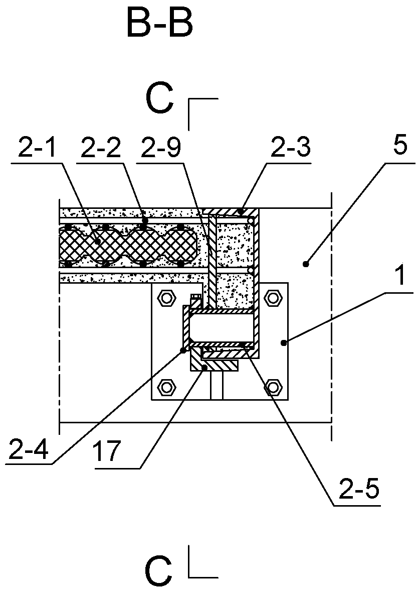
[0040] An additional elevator corridor bridge assembly includes a shaft support 1, a corridor plate 2, a building support 3 and the like. The corridor slab 2 is a prefabricated reinforced concrete hollow slab, and the two ends of its two sides are respectively provided with load-bearing shafts 2-5; the shaft support 1 is fixed on the elevator shaft 4, and an opening upward The groove I1-1 of the groove I1-1 is provided with a sealing plate I1-2 that matches with it and can close the groove I1-1; the building support 3 is fixed on the building beam 5 of the existing building, and the There is a groove II3-1 with an upward opening, and a sealing plate II3-2 that matches it and can close the groove II is also provided above it; the longitudinal section of the groove I and the longitudinal section of the groove I...


PUM


Abstract

The invention relates to an additional elevator gallery bridge assembly which comprises a shaft support seat, a gallery plate and a building support seat, wherein the gallery plate is a prefabricatedreinforced concrete hollow plate; force bearing shafts are respectively arranged at two ends of the two side edges of the gallery plate; the shaft fixed support seat is fixed on an elevator shaft; a first groove with an upward opening is formed in the shaft support seat; the building support seat is fixed on the existing building wall body; a second groove with an upward opening is formed in the building support seat; each of the longitudinal profile of the first groove and the longitudinal profile of the second groove is in a bell mouth shape; the bottom of the first groove is in a semicircular shape with the diameter identical to the diameter of the force bearing shaft, so that the force bearing shaft can rotate in the first groove; the bottom of the second groove is in a shape of a halflong circle; and the transverse distance of the second groove is greater than the diameter of the force bearing shaft, so that the force bearing shaft can rotate and transversely move in the second groove. The additional elevator gallery bridge assembly has the advantages that the weight of the gallery plate can be reduced; the transportation and the installation are convenient; the adverse influence of the shaft on the building structure can be reduced; and beneficial conditions are created for the safe operation of an additional elevator.

Description

technical field [0001] The invention relates to an elevator facility, in particular to an elevator bridge assembly and a construction method thereof, in particular to an elevator bridge assembly and an installation method thereof. Background technique [0002] With the arrival of my country's aging society, existing multi-storey residential buildings and office buildings need to add additional elevators so that the elderly can live and work. Building an additional elevator shaft frame and corridor next to the existing building, such as using the traditional construction method of cast-in-place concrete or welded steel structure, not only has problems such as long construction period, low work efficiency, fire hazard, environmental pollution, waste of materials, etc. And it is easy to interfere with the use of existing buildings, and cause many conflicts with building residents. At present, the elevator shaft has been basically prefabricated, but the bridge slab for walking ...

Claims


Application Information

Patent Timeline
IPC IPC(8): E04G23/02E04B1/38B66B11/00B66B7/00
CPCB66B7/00B66B11/0005E04B1/38E04G23/0266
Inventor 万勇李明董炜
Owner JIANGSU RUIYONG CONSTR ENG TECH
Why Eureka
Try Eureka