Oil-contained bearing

A bearing and oil tank technology, applied in the field of oil bearing design, can solve the problems of reduced oil storage volume, easy generation of clumps, rotating friction, etc., and achieve the effect of increasing oil storage volume, better rotating lubrication effect, and prolonging service life.

Inactive Publication Date: 2008-08-20
协禧微机电科技(昆山)有限公司
View PDF0 Cites 2 Cited by
  • Summary
  • Abstract
  • Description
  • Claims
  • Application Information

AI Technical Summary

Problems solved by technology

[0003] Looking back on the past, the applicant also filed a patent application in Taiwan on March 30, 2001 for an "oil return structure for fan spindle lubrication". Image 6 As shown, the oil bearing (30) in the oil return structure is provided with a perforation (32) in the body (31), a chamfer (33) is provided at the end edge of the body (31), and one end of the body (31) extends out The ring part (35), the oil groove (38) is formed in the ring part (35), and the corresponding grooves (34), (36) are opened on the body (31), and the bottom periphery of the oil bearing (30) is arranged Chamfer (37), although the oil bearing (30) has the function of lubricating the fan spindle, but because the outer diameter of the body (31) is larger than the ring part (35), and the length of the body (31) is larger than the length of the ring part (35) , so when the oil-impregnated bearing (30) is installed in the bushing, the tightening force of the inner wall of the bushing on the oil-impregnated bearing (30) will affect the relative The roundness of the inner wall of the perforation (32) in this section of length makes it easy to produce a beam center when the mandrel is pivoted, which hinders the rotation of the mandrel and produces rotational friction noise
[0004] Furthermore, the body length (31) of the above-mentioned oil-impregnated bearing (30) is greater than the length of the ring portion (35), causing the oil storage volume between the peripheral surface of the oil-impregnated bearing (30) and the shaft sleeve to decrease, and the groove (34) ( 36) are opposite to each other in a vertical straight line, which will easily cause the oil to flow out through the straight-line opposite grooves (34) (36). Therefore, although the above-mentioned oil bearing (30) can provide spindle lubrication and allow The assembly of the fan spindle is smoother, and it has the advantage of balancing the internal pressure of the oil storage tank with the outside world, but there is still room for further adjustment and improvement

Method used


Image

  • Oil-contained bearing
  • Oil-contained bearing
  • Oil-contained bearing

Examples


Embodiment Construction

[0027] The present invention will be further described below in conjunction with the accompanying drawings and specific embodiments.

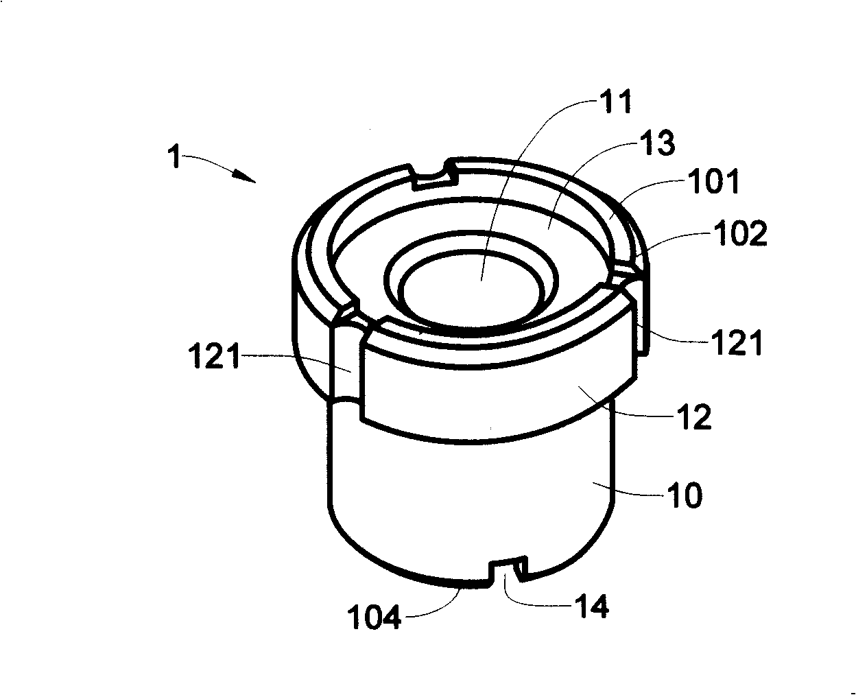
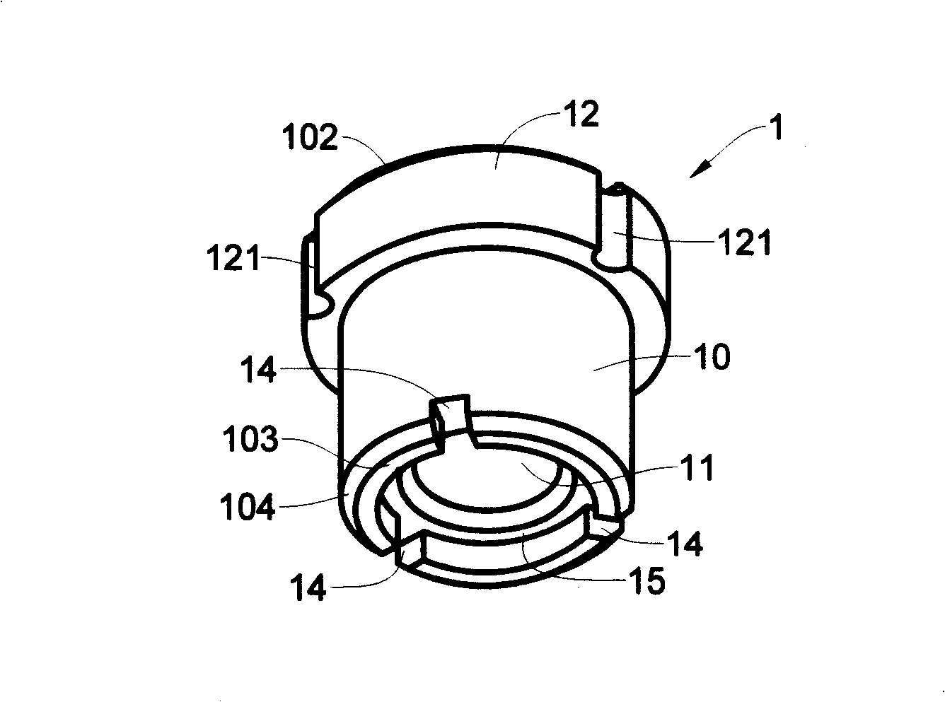
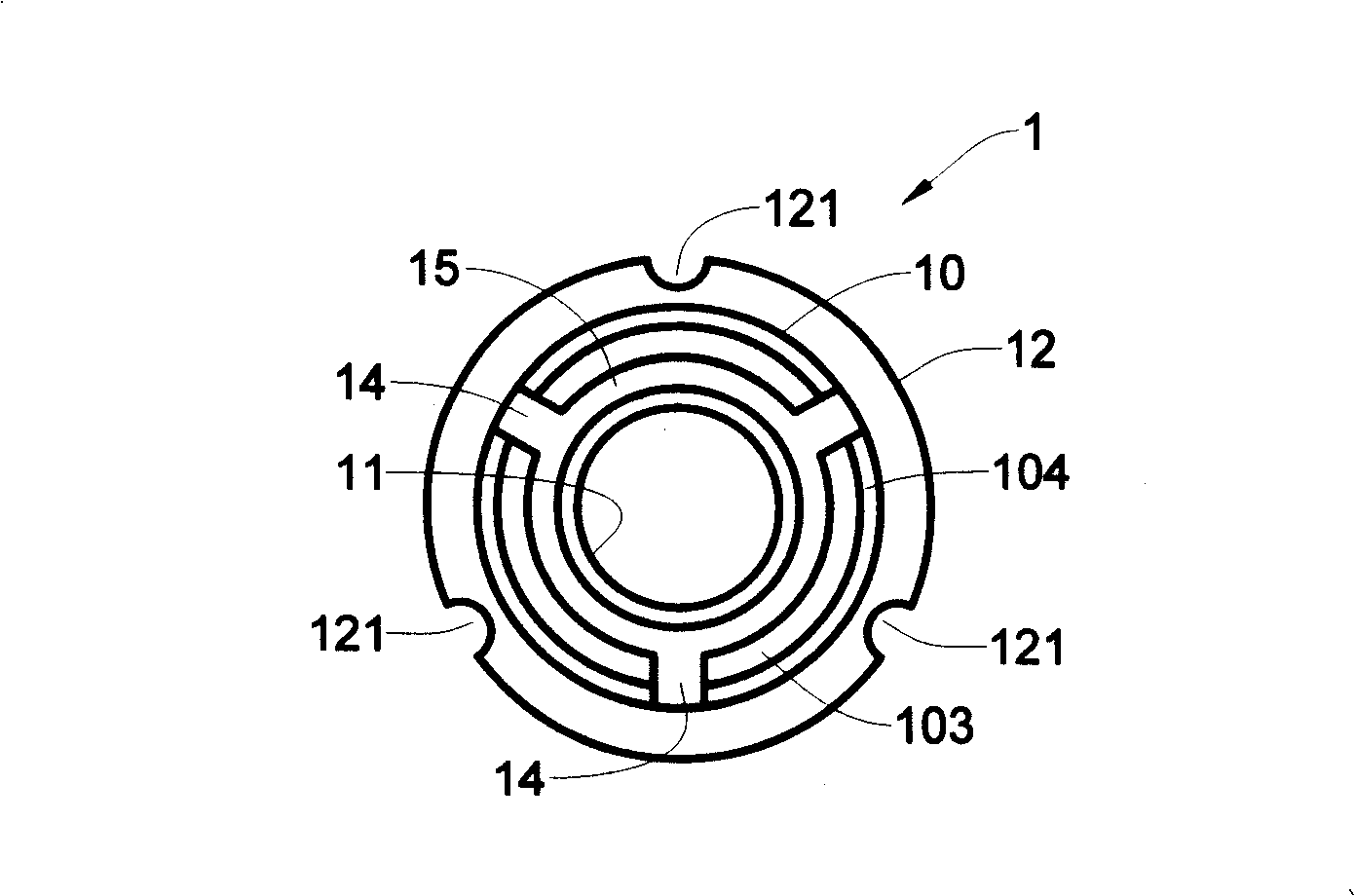
[0028] Cooperate with reference Figure 1 to Figure 4 As shown, wherein the oil-impregnated bearing (1) of the present invention has a cylindrical body (10), a perforation (11) is set in the body (10), and a crown with an enlarged diameter is formed at the upper edge of the body (10). part (12), the length of the crown (12) is less than the length of the body (10), and an annular groove (13) is set at the inner edge of the top of the body (10), the annular groove (13) is located in the crown (12), The surface of the crown (12) is provided with several grooves (121), and the bottom (103) of the body (10) is provided with an oil groove (15), and the periphery of the oil groove (15) is provided with several grooves (14), and the groove (14 ) and the groove (121) on the surface of the crown (12) form a dislocation shape.

[0029] The top (101) of...


PUM


Abstract

The invention relates to an oil bearing which is provided with a cylindrical body which is internally provided with a perforation; the upper circumferential edge of the body forms a crown with enlarged round diameter; the length of the crown is less than the length of the body; furthermore, the internal edge of the top end of the body is provided with a ring trough which is arranged in the crown; the surface of the crown is provided with a plurality of troughs; the bottom of the body is provided with an oil trough; the circumferential edge of the oil trough is provided with a plurality of troughs which are staggered with the troughs on the surface of the crown. By the design, the internal effect of the lacing force on the perforation of the oil bearing is reduced, thus reducing the lacing center situation; furthermore, the length of the body is more than that of the crown, therefore, the oil storage volume of the oil bearing inside a sleeve can be increased; furthermore, a plurality of troughs in staggered type which are arranged at the bottom of the body and on the surface of the crown can prevent the overflowing and dispersing of oil products.

Description

technical field [0001] The invention relates to an oil-impregnated bearing, especially a body whose longitudinal length is greater than the length of the crown, thereby increasing the oil storage capacity and reducing the tightening force to produce a beam center for the mandrel, and has mutually misaligned grooves, which can Oil-impregnated bearing design to prevent oil spillage. Background technique [0002] In order to prevent the lubricating oil from the oil-impregnated bearing from being lost downward when the spindle of the fan rotor rotates, today's fans are designed with a closed oil storage tank at the bottom of the outer casing, and an oil-impregnated bearing is installed in it. The mandrel of the fan rotor can be pivoted in the oil bearing, and when rotating, the lubricating oil released from the oil bearing can be used to lubricate the mandrel when it rotates. [0003] Looking back on the past, the applicant also filed a patent application in Taiwan on March 30,...

Claims


Application Information

Patent Timeline
Patent Type & Authority Applications(China)
IPC IPC(8): F16C33/10
Inventor 谢新茂许文霖简之荣
Owner 协禧微机电科技(昆山)有限公司
Why Eureka
Try Eureka