Optical storage read-write equipment and its application in economy domain computerization
A technology for optical storage and reading and writing devices, applied in beam guiding devices, data processing applications, instruments, etc., can solve the problems of data authenticity not being guaranteed, data being easily tampered with, and artificial tampering, etc., to avoid reading and writing speed. , the effect of short data access time and low accuracy
- Summary
- Abstract
- Description
- Claims
- Application Information
AI Technical Summary
Problems solved by technology
Method used
Image
Examples
Embodiment 1
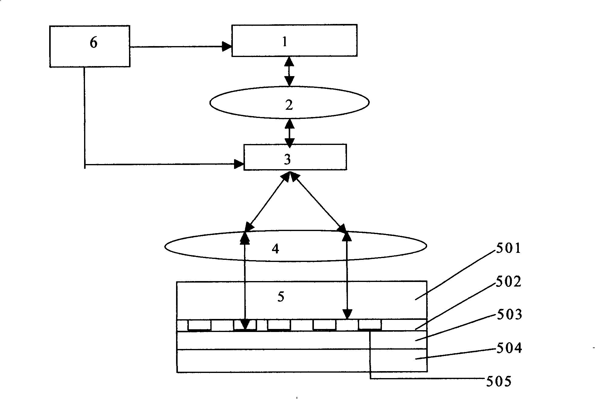
[0128] Embodiment 1: The laser-scanning optical memory read-write device is composed of software and hardware, and the software includes: a laser-scanning optical memory read-write device driver and a laser scanner control program. Hardware includes: optical memory, adapter cards and laser scanners.
[0129] The laser scanner driver is a device management program in the operating system software, just like an ordinary CD driver. In microcomputer systems, this part is often solidified in the ROM of the system board. The device management program in the operating system software includes: I / O scheduler, device read / write management program, buffer management program, and device driver. Under the control of the laser scanner driver, issue operation commands to the adapter card, recycle relevant status information, accept interrupt requests and DMA requests, send and receive data information, etc. At the level of the driver program, it will involve the physical characteristics a...
Embodiment 2
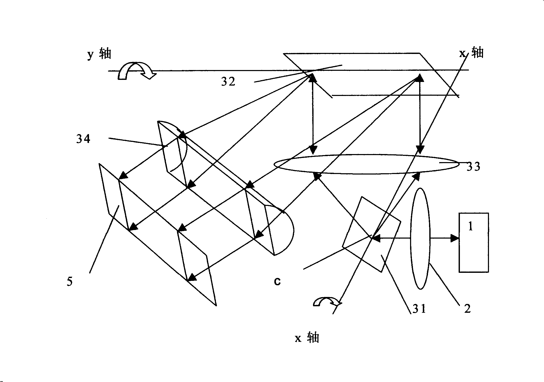
[0138] Embodiment 2: Another preferred embodiment of the laser scanning optical card reading and writing device of the present invention is as follows image 3As shown, the device has an optical read-write head 1 fixed, and a collimating lens 2 and a simple double-mirror system are installed in front of the optical read-write head 1 . The simple double-mirror system has two reflecting mirrors, an x-axis reflecting mirror 31 and a y-axis reflecting mirror 32, a convex lens 33 is installed between the x-axis reflecting mirror 31 and the y-axis reflecting mirror 32, and a convex lens 33 is installed between the y-axis reflecting mirror 32 and the optical memory 5 A convex cylindrical lens 34 is installed between them. The scanning axis of the x-axis reflector 31 (i.e. the center of rotation of the mirror surface) intersects the optical axis of the convex lens 33 at point c, which is the light deflection point of the first scanner 31, and point a is also the front focus of the con...
Embodiment 3
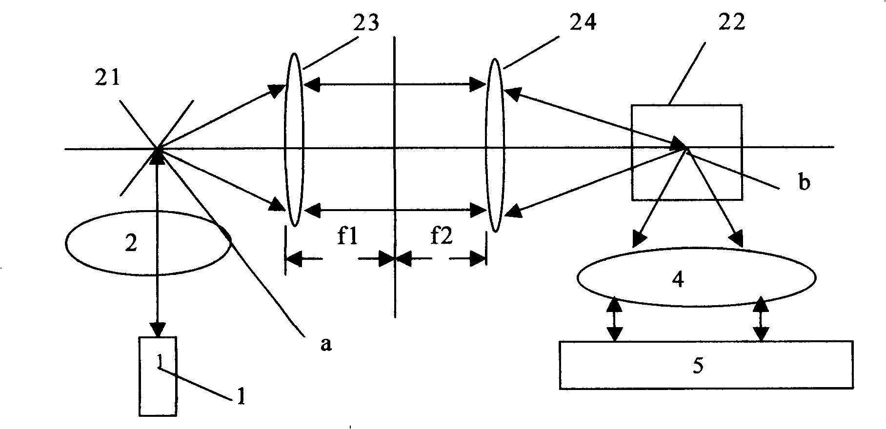
[0139] Embodiment 3: Another preferred embodiment of the laser scanning optical card reading and writing device of the present invention is as follows Figure 4 As shown, the laser scanning type optical memory read-write device has a plurality of optical heads, and there are multiple areas or optical tracks corresponding to the number of optical heads on the optical memory. The optical structure of the laser scanner uses a relay lens system, and these optical heads can be arranged arbitrarily. Either on one plane or not on one plane. As long as the light beam emitted by each optical head hits the light deflection point of the first scanner, that is, the focus of the scanning axis and the optical axis of the lens, and the scanning range is within the first lens. An arrangement of the bald heads is: a part of the bald heads are arranged on a plane A, such as Figure 4 The arrangement position of the optical head 141, 142, 143 in. And another part of the bald head is arranged o...
PUM
 Abstract
Description
Claims
Application Information
 - R&D
- Intellectual Property
- Life Sciences
- Materials
- Tech Scout
- Unparalleled Data Quality
- Higher Quality Content
- 60% Fewer Hallucinations
Browse by: Latest US Patents, China's latest patents, Technical Efficacy Thesaurus, Application Domain, Technology Topic, Popular Technical Reports.
© 2025 PatSnap. All rights reserved.Legal|Privacy policy|Modern Slavery Act Transparency Statement|Sitemap|About US| Contact US: help@patsnap.com


