Light emitting device

A light-emitting device and light source technology, which is applied in the direction of lighting devices, electroluminescent light sources, fixed lighting devices, etc., can solve problems such as increased product costs, achieve the effects of reduced assembly hours, reduced costs, and prevented increased losses

Inactive Publication Date: 2008-08-20
KOITO MFG CO LTD
View PDF1 Cites 22 Cited by
  • Summary
  • Abstract
  • Description
  • Claims
  • Application Information

AI Technical Summary

Problems solved by technology

For example, when configuring a system in which one circuit corresponds to a plurality of LEDs, it is necessary to configure a driving circuit corresponding to the type of LED, or to configure a driving circuit corresponding to the type of vehicle, and the cost of the product increases as the circuit development cost increases.

Method used


Image

  • Light emitting device
  • Light emitting device
  • Light emitting device

Examples


Embodiment Construction

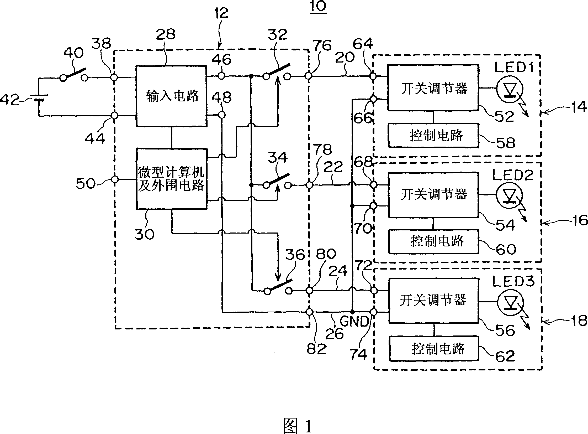
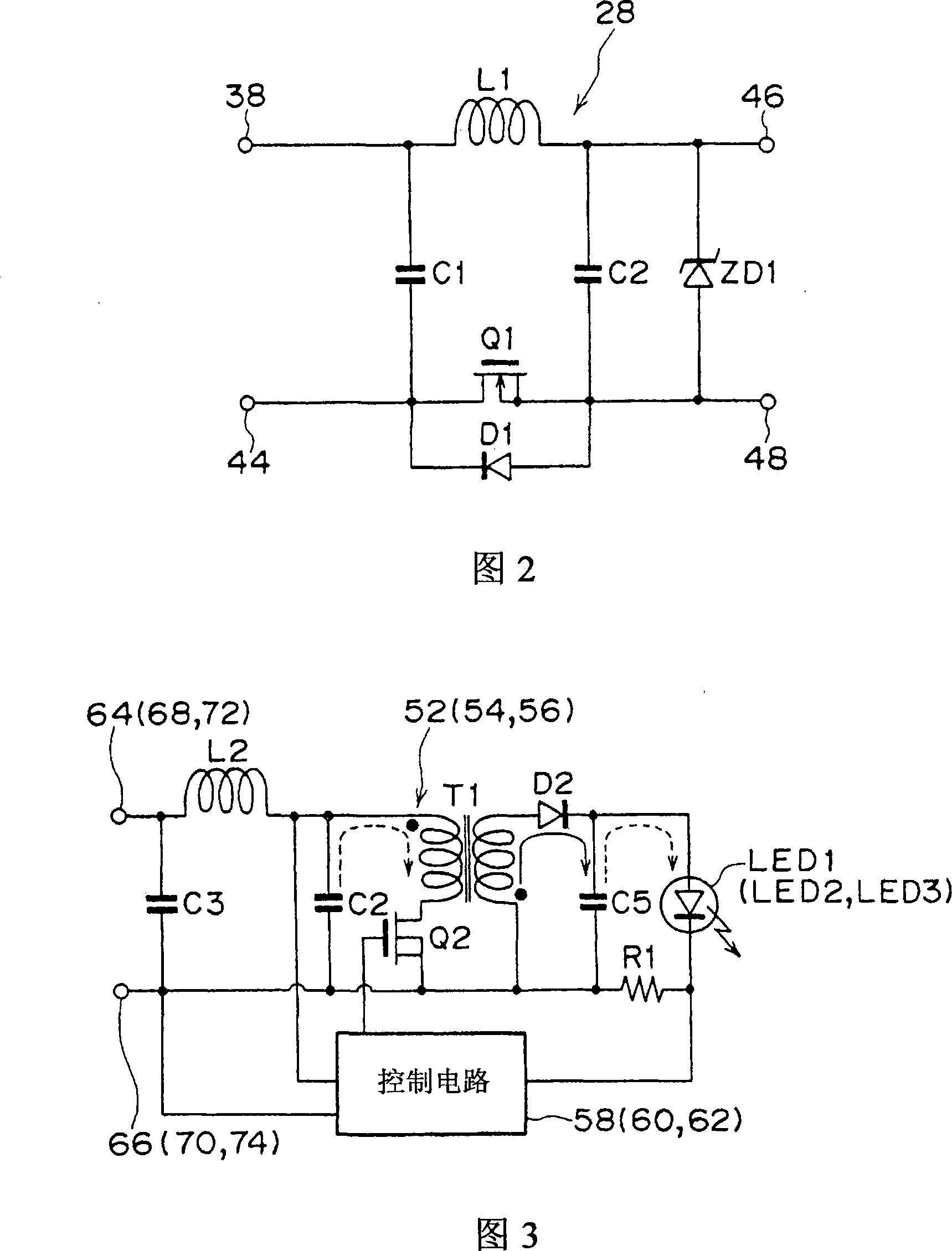
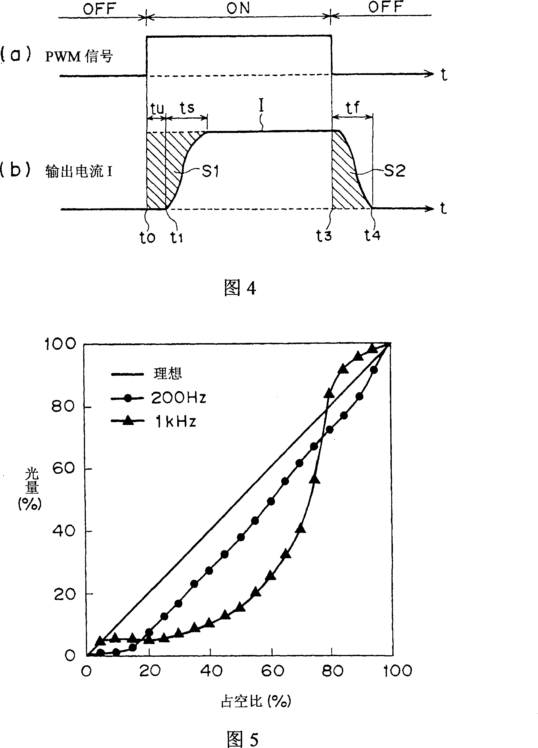
[0032] Hereinafter, one embodiment of the present invention will be described based on the drawings. Fig. 1 is a structural block diagram showing a light emitting device according to a first embodiment of the present invention, Fig. 2 is a circuit configuration diagram of an input circuit, and Fig. 3 is a circuit configuration diagram showing a switching regulator and a control circuit according to a first embodiment of the present invention , Fig. 4 is a waveform diagram illustrating the relationship between the PWM signal and the output current of the switching regulator, Fig. 5 is a characteristic diagram illustrating the relationship between the duty ratio of the PWM signal and the amount of light, and Fig. 6 is a diagram showing the The circuit configuration diagram of the switching regulator and the control circuit of the second embodiment of the invention, Fig. 7 is a circuit configuration diagram showing the switching regulator and the control circuit of the third embod...


PUM


Abstract

A light emitting device includes multiple light units each of which includes a semiconductor light source, and a current supply control means for controlling supply of current to the semiconductor light source. A control unit includes a control signal generation means for generating and providing a control signal. The light emitting device also includes switching means for controlling feeding from a DC power source to a corresponding one of the light units in response to the control signal. Each of the switching means is coupled to a corresponding one of the light units through a feed line.

Description

technical field [0001] The present invention relates to a light-emitting device, and more particularly, to a light-emitting device configured to be used as a vehicle lamp. Background technique [0002] Currently, it is known to use a semiconductor light emitting element such as an LED (Light Emitting Diode) as a light source as a vehicle lamp. When configuring a vehicle lamp using LEDs as a light source, since the lamp is the eyes of the vehicle and its appearance is important, its specifications are divided into many types. For example, depending on the vehicle (vehicle type), there may be various changes in the following: the number of LEDs used is different, the shape or size of the lamp itself is different, or the vehicle used to control the turning on / off or brightness of each LED is different. The circuit structure of the lighting control circuit of the lamp is different. [0003] If the circuit development is carried out with one specification for each variety for v...

Claims


Application Information

Patent Timeline
Patent Type & Authority Applications(China)
IPC IPC(8): H05B37/02F21S8/10F21W101/02F21Y101/02F21W107/10H01L33/00
CPCY02B20/346H05B33/0815H05B33/0851H05B45/382Y02B20/30H05B45/3725H05B45/10H05B45/375H05B45/38H05B45/385H05B31/50
Inventor 盐津文规难波高范伊藤昌康
Owner KOITO MFG CO LTD
Why Eureka
Try Eureka