Apparatus for forming pipe material

A tube and forming surface technology, applied in forging/pressing/hammer devices, forming tools, mechanical equipment, etc., can solve the problems of limited shape, large device volume, and uneven force, and achieve uniform forming pressure and reduce process. effect of quantity

Inactive Publication Date: 2008-08-20
HONDA MOTOR CO LTD
View PDF2 Cites 3 Cited by
  • Summary
  • Abstract
  • Description
  • Claims
  • Application Information

AI Technical Summary

Problems solved by technology

Therefore, the number of hydraulic cylinders increases, the device is bulky, and the force acting on each split mold may not be uniform
In addition, necking and chiseling cannot be performed at the same time
[0007] On the other hand, the forming device introduced in Patent Document 2 is a device for convex processing. Therefore, the pressurized fluid is supplied to the inside of the pipe, and the pipe is enlarged and formed outward. Although the forming pressure is uniformly controlled in the pipe, it is not suitable for necking. Machining and Chiseling
In addition, when the pipe material is a double pipe, restrictions increase, and the shapes that can be formed are limited.

Method used


Image

  • Apparatus for forming pipe material
  • Apparatus for forming pipe material
  • Apparatus for forming pipe material

Examples


Embodiment Construction

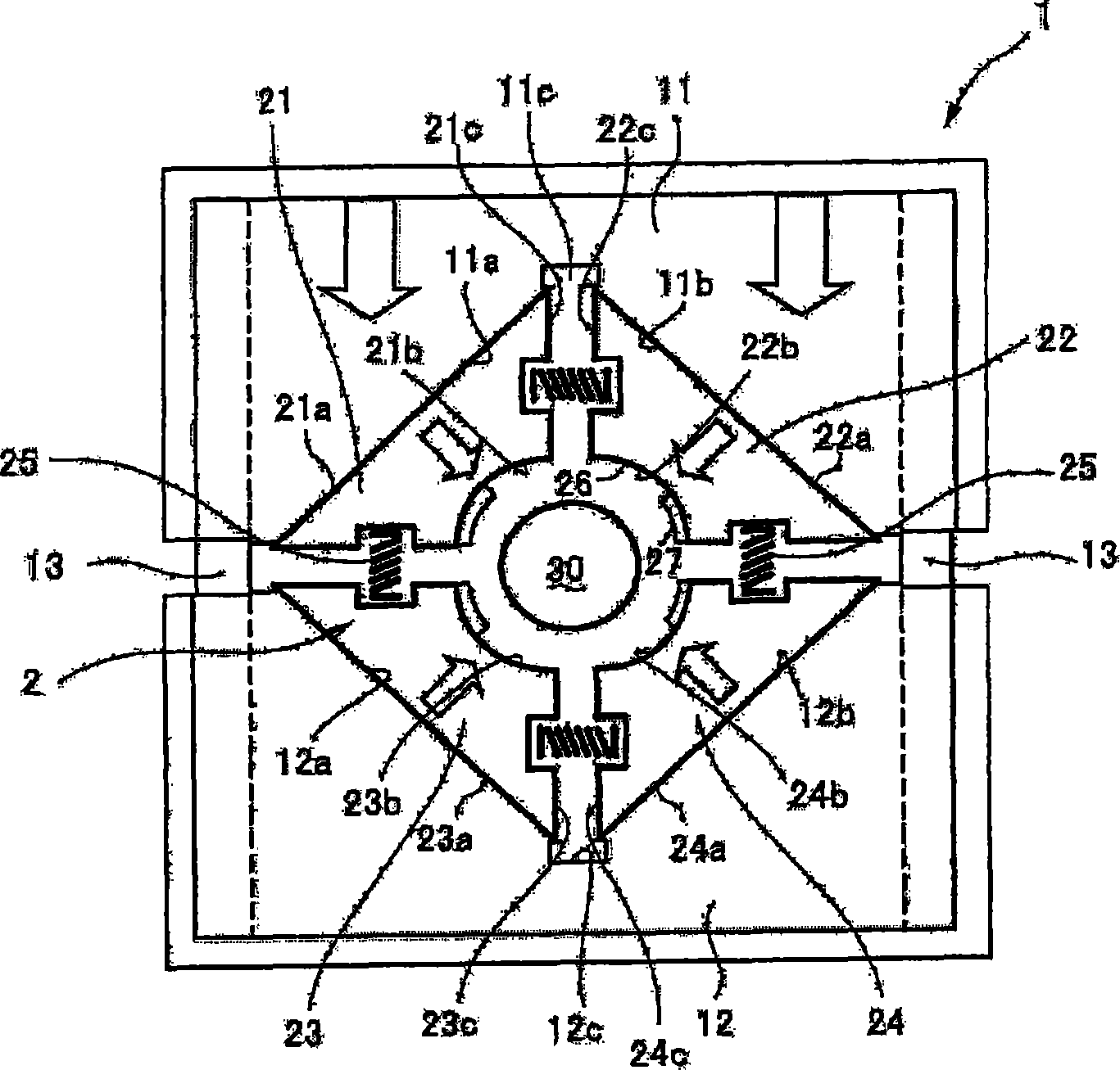
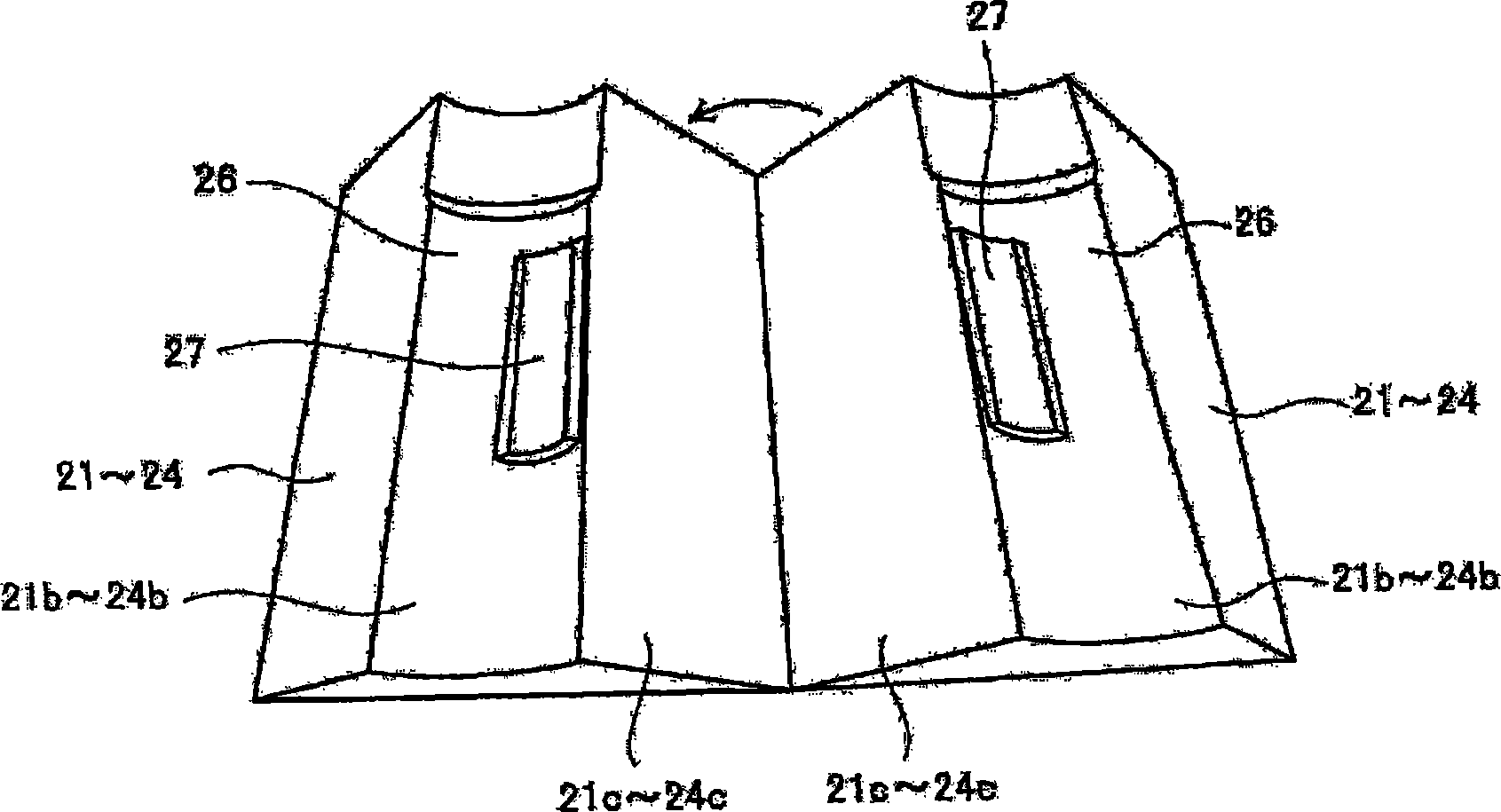
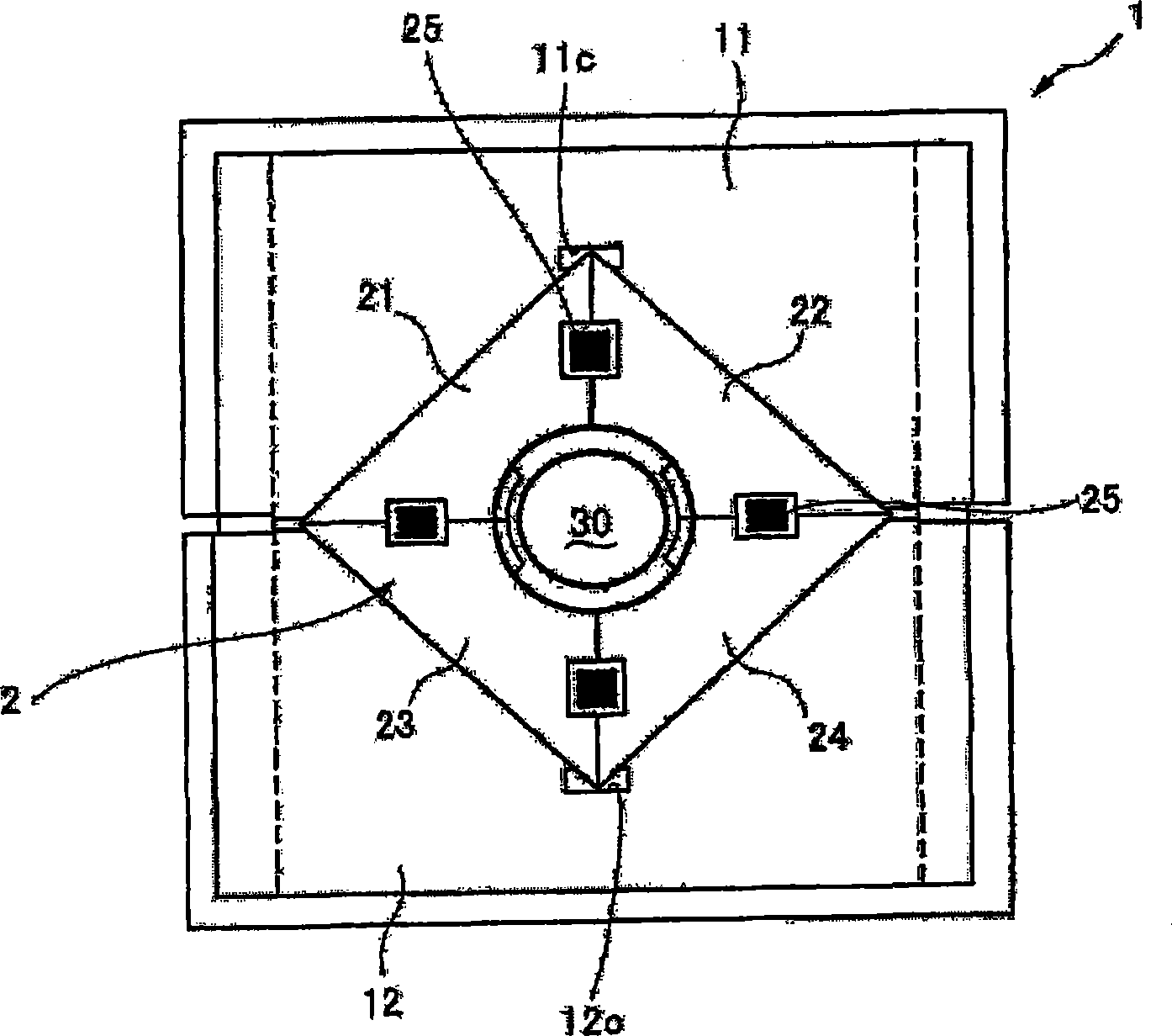
[0020] Hereinafter, preferred embodiments of the present invention will be described in detail with reference to the accompanying drawings. here, figure 1 It is a front view of the mold opening state of the forming apparatus of the present invention. figure 2 It is a perspective view of one of the four split molds constituting the inner mold of the molding apparatus. image 3 It is a front view of the mold-opening state of the molding device of the above-mentioned molding device. Figure 4 It is a view showing the end of the exhaust pipe after molding.

[0021] The forming device includes an outer mold 1 and an inner mold 2 . The outer mold 1 is composed of upper and lower split molds 11 and 12. The upper split mold 11 engages with the sliding member 13 and is driven by an unshown hydraulic cylinder or electric motor to move forward and backward relative to the lower split mold 12.

[0022] The smooth sliding surfaces 11a and 11b forming an inverted V-shape are formed und...


PUM


Abstract

The invention provides a molding device that a plurality of split dies can be equally clamped with a single drive source. In subjecting a tube material to drawing and caulking, a tube material is first externally inserted into a cored bar (30). In this case, upper and lower split dies (11, 12) constituting an external die (1) are in a mold opened state. From this state, an upper split die (11) constituting an external die (1) is moved downwardly. This allows four split dies (21, 22, 23, 24) constituting an inner die (2) to evenly move toward the center, and an exhaust pipe is subjected to drawing and caulking simultaneously by molding faces (26, 27) formed on the inner face of the four split dies.

Description

technical field [0001] The present invention relates to a forming device capable of performing necking (twisting) processing and / or caulking (kashi) processing of pipe materials, especially double pipes such as exhaust pipes, at the same time. Background technique [0002] Patent Documents 1 and 2 describe an apparatus capable of forming a pipe between dies. As a forming device for crimping a ground terminal as a tubular member, Patent Document 1 describes a structure in which punches for embossing are attached to six divided dies that form hexagonal shaped portions during die clamping. [0003] In addition, as a protrusion forming device, Patent Document 2 introduces a structure in which an inner mold is installed in an outer mold, and a forming part is installed in the inner mold. [0004] Patent Document 1: JP-A-2002-233918 [0005] Patent Document 2: JP-A-2003-251418 [0006] In the forming apparatus described in Patent Document 1, each divided die is moved forward an...

Claims


Application Information

Patent Timeline
Patent Type & Authority Applications(China)
IPC IPC(8): B21D37/02B21D39/04B21D41/04B21D53/84
CPCB21J5/12B21J13/025
Inventor 泉英治大桥和哉
Owner HONDA MOTOR CO LTD
Why Eureka
Try Eureka