Step wing used for ejection type glider model

A glider and catapult technology, applied in toy planes, entertainment, toys, etc., can solve the problems of wasting time, difficult to master precision, and laborious, and achieve the effect of reducing wing weight, simple production, and precise processing and control.

Pending Publication Date: 2017-06-30
TIANJIN NORMAL UNIVERSITY
View PDF6 Cites 0 Cited by
  • Summary
  • Abstract
  • Description
  • Claims
  • Application Information

AI Technical Summary

Problems solved by technology

The wings of a traditional catapult glider generally adopt a flat-convex airfoil, such as figure 1 As shown, it needs to be carefully polished during production, which is a waste of time; in addition, its accuracy is difficult to grasp, and the airfoil of the wing needs to be made in advance, which requires grinding tools or a unified production line, which is very labor-intensive

Method used


Image

  • Step wing used for ejection type glider model
  • Step wing used for ejection type glider model
  • Step wing used for ejection type glider model

Examples


Embodiment Construction

[0020] The technical solution of the present invention will be further described below in conjunction with the accompanying drawings.

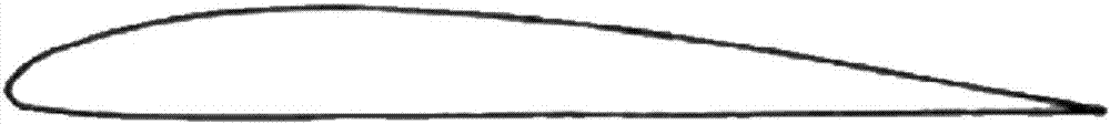
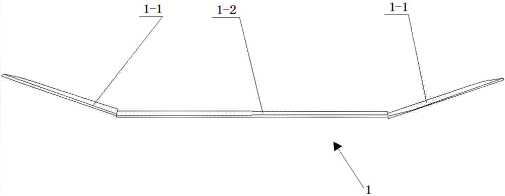
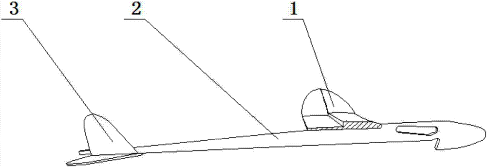
[0021] Such as Figure 2-6 As shown, a wing 1 and an empennage 3 are installed on the fuselage 2, and a through hole (not shown) and a hook for ejection (not shown in the figure) for adjusting the center of gravity of the catapult glider model are formed on the front portion of the fuselage. show). The wing adopts three-section installation, and the wing is composed of the middle section 1-2 of the wing and 2 wing tips 1-1, such as figure 2 As shown, the middle section of the wing is horizontally installed on the fuselage through a mortise and tenon mechanism, which makes the connection between the wing and the fuselage very simple and precise, and the manual connection speed only takes 20 seconds; the two wingtips are respectively bonded It is fixed at both ends of the middle section of the wing, and the dihedral angle of the wingtip is 20...


PUM


Abstract

The invention discloses a step wing used for an ejection type glider model. The step wing comprises a wing body, a stair is formed on the upper surface of the wing body in the length direction and located at the position of 45-55% wing chord length, and the step height of the stair is 4-6% of the wing chord length. The step wing has the advantages that the stair makes the wing into the step wing, the step wing is easy to manufacture, time and labor are saved, airfoil processing and control are precise, and the weight of the wing is reduced. If the step wing is installed on the ejection type glider model, the lift-drag ratio of the wing can be improved, and the stalling attack angle of the wing is increased.

Description

technical field [0001] The invention belongs to the technical field of aircraft for scientific and technological activities, and in particular relates to a stepped wing for a catapult glider model. Background technique [0002] Catapult models have a long history as toys or as teaching aids for beginners in aviation. The wings of a traditional catapult glider generally adopt a flat-convex airfoil, such as figure 1 As shown, it needs to be polished carefully during production, which is a waste of time; in addition, its accuracy is difficult to grasp, and the airfoil of the wing needs to be made in advance, which requires grinding tools or a unified production line, which is very labor-intensive. Contents of the invention [0003] Aiming at the deficiencies in the prior art, the object of the present invention is to provide a stepped wing for a catapult glider model. [0004] The purpose of the present invention is achieved through the following technical solutions. [00...

Claims


Application Information

Patent Timeline
Patent Type & Authority Applications(China)
IPC IPC(8): A63H27/18A63H27/20
CPCA63H27/02
Inventor 郭树冠
Owner TIANJIN NORMAL UNIVERSITY
Why Eureka
Try Eureka