Supercharge Your Innovation With Domain-Expert AI Agents!

Combined thermoelectricity and magnetic refrigeration system

A technology of refrigeration system and thermoelectric element, which is applied in the direction of refrigerator, refrigeration and liquefaction, energy-saving heating/cooling, etc., and can solve the problem of low response

Inactive Publication Date: 2010-12-22
CARRIER CORP
View PDF0 Cites 0 Cited by
  • Summary
  • Abstract
  • Description
  • Claims
  • Application Information

AI Technical Summary

Problems solved by technology

The response of the system to different requirements is usually low due to the complex machine operation associated with the vapor compression cycle

Method used


Image

  • Combined thermoelectricity and magnetic refrigeration system
  • Combined thermoelectricity and magnetic refrigeration system
  • Combined thermoelectricity and magnetic refrigeration system

Examples


Embodiment Construction

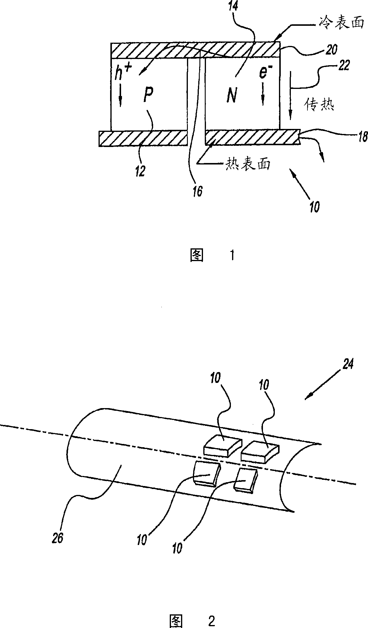
[0036] refer to figure 1 , which shows a cross-sectional view of a thermoelectric element denoted by reference numeral 10 . Thermoelectric element or device 10 is preferably a solid state device. The device 10 has a first P-type semiconductor 12 and a second N-type semiconductor 14 (with electrons as charge carriers). The current from the power source is passed to the P-type semiconductor 12 through the N-type semiconductor 14 .

[0037] When current is passed as indicated by reference arrow 16 , heat is removed from surface 20 and transferred through thermoelectric device 10 and then stored to second surface 18 of the thermoelectric device as indicated by arrow 22 . The heat removed from the surface 20 causes heat to be absorbed from the adjacent environment by the working fluid in contact with the cold surface 20 . Similarly, heat generated at surface 18 is dissipated through the heat transfer medium. Such thermoelectric devices 10 are well known and understood by those ...


PUM


Abstract

A refrigeration system has a compartment and a first cooling device. The first cooling device cools the compartment and generates a magnetic field. The refrigeration system also has a second device. The second device uses the generated magnetic field for additional cooling to the compartment.

Description

technical field [0001] The present invention relates to temperature control of compartments. More specifically, the present invention relates to a magnetic refrigeration system that uses a magnetic field generated by a plurality of thermoelectric elements wound into a configuration. Background technique [0002] Temperature control systems for heating and cooling devices are known in the art. Such known systems use a vapor compression cycle to provide cooling. Typically, refrigerant in the vapor phase is pumped from the evaporator by a compressor. This refrigerant is then compressed into a superheated vapor. High-pressure gas refrigerant absorbing heat is sent to the condenser. The refrigerant vapor condenses to a high-pressure liquid by transferring heat from the refrigerant to a low-temperature radiator. The condensed refrigerant liquid is circulated to the throttle valve. The throttle valve allows the pressure to drop to a lower level and the refrigerant enters the ...

Claims


Application Information

Patent Timeline
Patent Type & Authority Patents(China)
IPC IPC(8): F25B21/00F25B21/02F25B7/00
CPCH01L23/473Y02B30/66F25B21/00H01L2924/0002Y02B30/00H01L2924/00
Inventor 陈磊M·R·雅沃洛夫斯基于笑梅
Owner CARRIER CORP
Features
  • R&D
  • Intellectual Property
  • Life Sciences
  • Materials
  • Tech Scout
  • Unparalleled Data Quality
  • Higher Quality Content
  • 60% Fewer Hallucinations
Learn More