Combination Thermo-Electric and Magnetic Refrigeration System

Inactive Publication Date: 2009-05-28
CARRIER CORP
View PDF8 Cites 18 Cited by
  • Summary
  • Abstract
  • Description
  • Claims
  • Application Information

AI Technical Summary

Problems solved by technology

Due to the complex mechanical operations associated with the vapor compression cycle, the system response to varied demand is typically slow.
However, a known problem in the art is that the one or more thermoelectric devices generate a magnetic field.
This magnetic field is known

Method used


Image

  • Combination Thermo-Electric and Magnetic Refrigeration System
  • Combination Thermo-Electric and Magnetic Refrigeration System
  • Combination Thermo-Electric and Magnetic Refrigeration System

Examples


Embodiment Construction

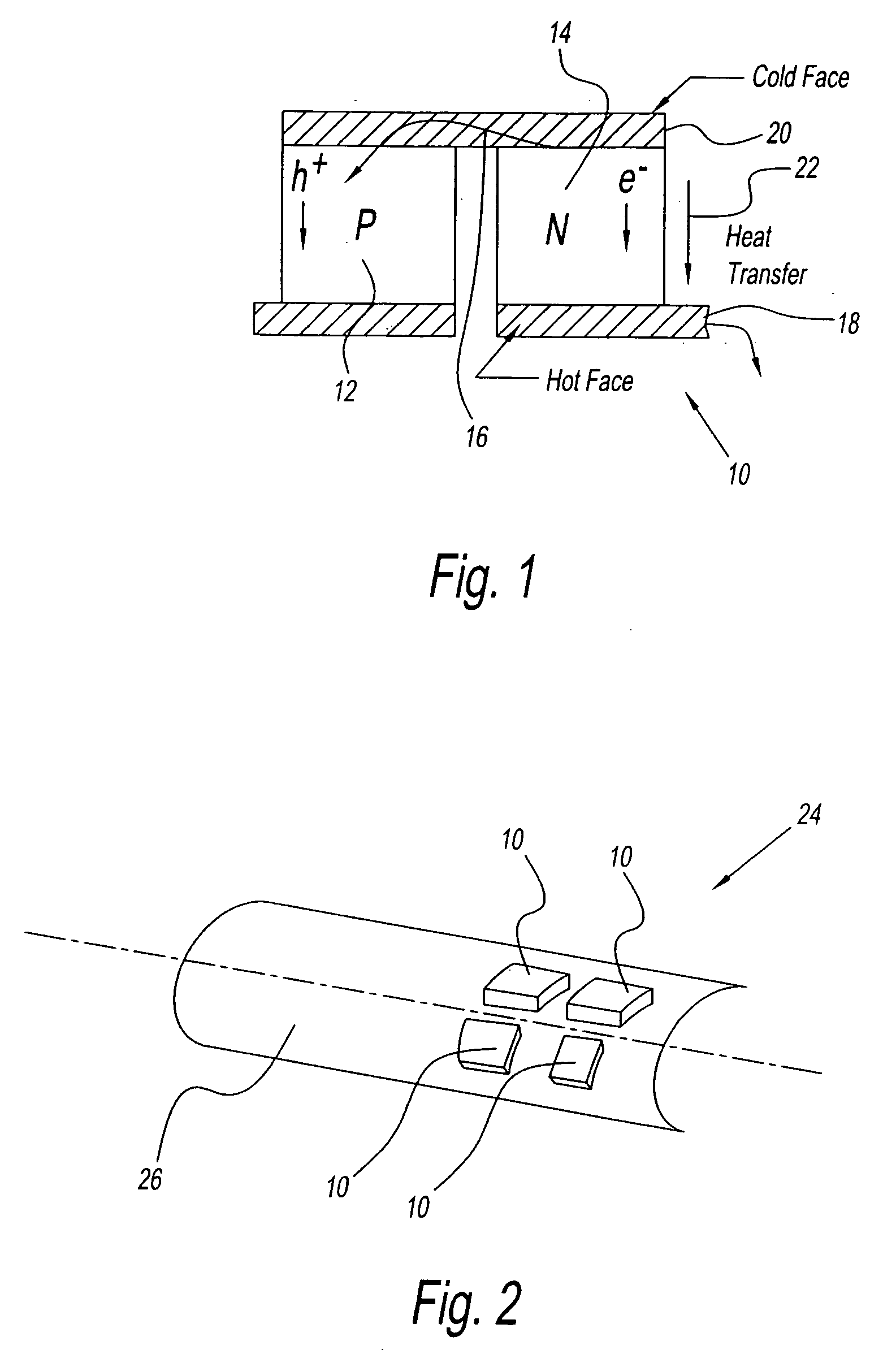
[0026]Referring to FIG. 1, there is shown a cross sectional view of a thermoelectric element shown as reference numeral 10. The thermo-electric element or device 10 is preferably a solid state device. The device 10 has a first P type semiconductor 12 and a second N type semiconductor 14 with an electron as a charge carrier. Current from a power supply is passed through the N type semiconductor 14 to the P type semiconductor 12.

[0027]When current passes therethrough as indicated by reference arrow 16, heat is removed from surface 20 and transferred through the thermoelectric device 10, and then deposited to a second surface 18 of the thermoelectric device as indicated by arrow 22. The heat removal from the surface 20 causes the absorption of heat from the adjacent environment through a working fluid in contact with the cold surface 20. Likewise, the heat generated at surface 18 is ejected through a heat transfer medium. This thermoelectric device 10 is well known and is understood by...


PUM


Abstract

A refrigeration system has a compartment and a first cooling device. The first cooling device cools the compartment and generates a magnetic field. The refrigeration system also has a second device. The second device uses the generated magnetic field for additional cooling to the compartment.

Description

BACKGROUND OF THE INVENTION[0001]1. Field of the Invention[0002]The present invention relates to a temperature control for a compartment. More particularly, the present invention relates to a magnetic refrigeration system that uses a magnetic field generated from a number of thermoelectric elements that are wound in a configuration.[0003]2. Description of the Related Art[0004]Temperature control systems for heating and cooling devices are known in the art. Such known systems use a vapor compression cycle to provide cooling. Typically the refrigerant in vapor phase is pumped from the evaporator by a compressor. The refrigerant is then compressed to a superheated vapor. The high-pressure gaseous refrigerant that absorbs the heat is sent to a condenser. The refrigerant vapor is condensed to high-pressure liquid by transferring heat from the refrigerant to a heat sink that has lower temperature. The condensed refrigerant liquid is circulated to a throttling valve. The throttling valve r...

Claims


Application Information

Patent Timeline
IPC IPC(8): F25B21/02
CPCF25B21/00H01L23/473Y02B30/66H01L2924/0002H01L2924/00Y02B30/00
Inventor CHEN, LEIJAWOROWSKI, MARK R.YU, XIAOMEI
Owner CARRIER CORP
Why Eureka
Try Eureka