
Intrauterine device shape change monitoring system

A technology of intrauterine device and monitoring system, which is applied in the field of deformation monitoring system of intrauterine device in female human body, can solve problems such as shedding, contraceptive failure, female body injury, etc., achieves convenient placement and removal, ingenious design, and avoids injury Effect

Inactive Publication Date: 2008-08-27
SICHUAN UNIV +2
View PDF0 Cites 3 Cited by
  • Summary
  • Abstract
  • Description
  • Claims
  • Application Information

AI Technical Summary

Problems solved by technology

However, when the doctor chooses a matching IUD, it is often determined based on some external information of the woman obtained, such as reproductive status, height, etc., and the actual size of the female's uterine cavity, the IUD in the uterus, etc. Therefore, about 10% of the IUDs chosen to be placed are not suitable for the shape and force of the uterine cavity, and they fall off or deviate from their effective contraceptive position, which eventually leads to contraception. Failure, which not only brings great harm to the female body, but also affects the effectiveness of IUD contraception

Method used


Image

  • Intrauterine device shape change monitoring system
  • Intrauterine device shape change monitoring system
  • Intrauterine device shape change monitoring system

Examples


Embodiment 1

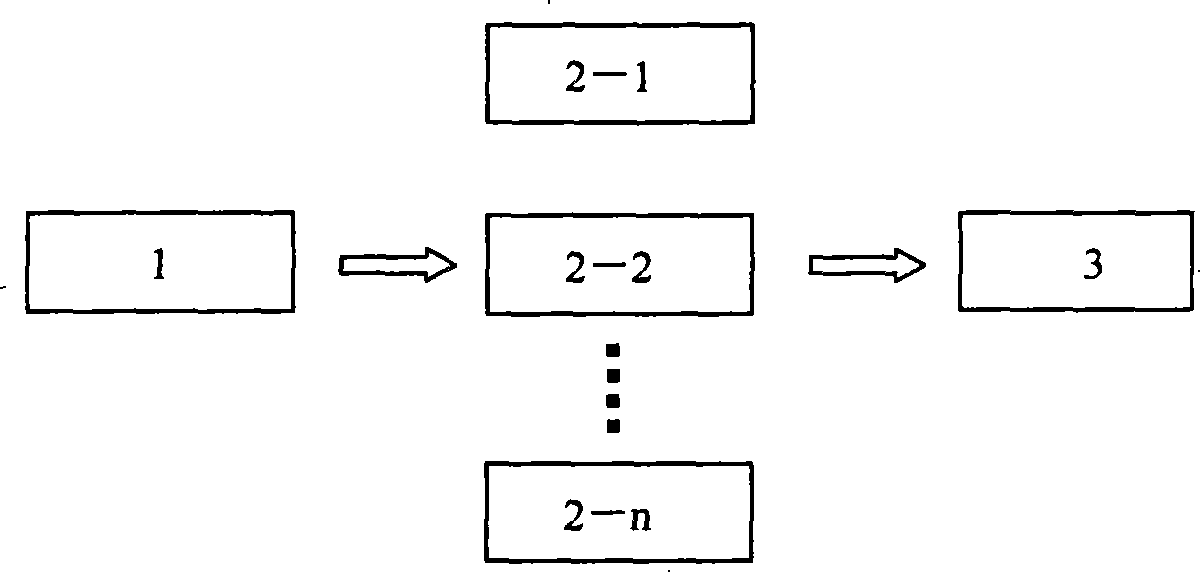
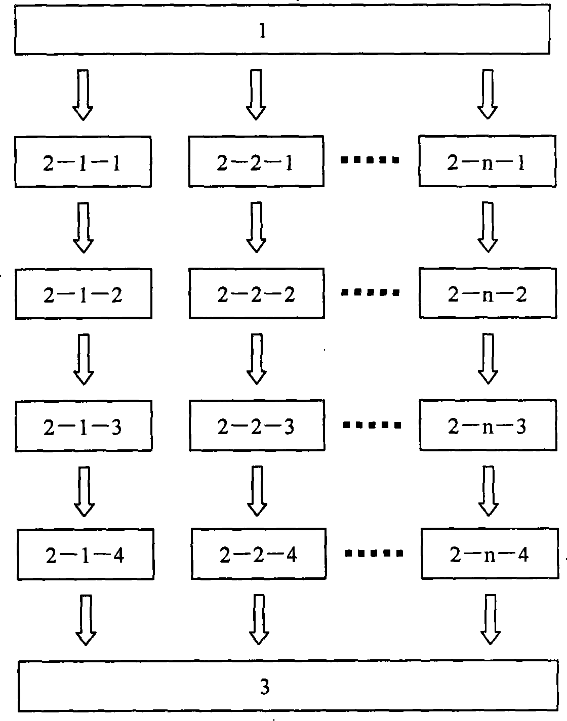
[0043] Such as figure 1 As shown, the IUD deformation monitoring system given in this embodiment is composed of an IUD sensor 1, a pre-signal conditioning module 2-n, a power circuit and a computer system 3. The IUD sensor 1 is sequentially connected with the pre-signal conditioning modules 2-n and the computer system 3 through the wires and connectors therebetween.

[0044] The IUD sensor 1 present embodiment is the deformation sensor of the IUD, which is specifically composed of the IUD 4 and the metal coil 5, see Figure 4 , 8. IUD 4 is commercially available, and large, medium and small models can be selected as required. The metal coil 5 in this embodiment consists of 3 groups, which are respectively wound by 13 copper core wires with a diameter of 0.06mm and the outer surface is covered with an insulating layer, and are divided into upper, left and right according to the shape of the palace-shaped IUD 1. Three-way horizontal bonding on the body of the IUD 4 plane sid...

Embodiment 2

[0059] Such as figure 1 As shown, the IUD deformation monitoring system given in this embodiment is composed of an IUD sensor 1, a pre-signal conditioning module 2-n, a power circuit and a computer system 3. The IUD sensor 1 is sequentially connected with the pre-signal conditioning modules 2-n and the computer system 3 through the wires and connectors therebetween.

[0060] The IUD sensor 1 present embodiment is also a deformation sensor of the IUD, and the deformation sensor of the IUD is also composed of the IUD 4 and the metal coil 5, and is covered and fixedly connected by natural latex 8, see Figure 4 , 5 , 8, but because its structure is exactly the same as that of Example 1, it is omitted. The uterine cavity deformation sensor of this embodiment is different from that of Embodiment 1 in that the metal coils 5 of this embodiment are respectively wound by 15 turns of a copper core wire with a diameter of 0.05 mm and an outer surface covered with an insulating layer. ...

Embodiment 3

[0063] Such as figure 1 As shown, the IUD deformation monitoring system given in this embodiment is composed of an IUD sensor 1, a pre-signal conditioning module 2-n, a power circuit and a computer system 3. The IUD sensor 1 is sequentially connected with the pre-signal conditioning modules 2-n and the computer system 3 through the wires and connectors therebetween.

[0064] The IUD sensor 1 present embodiment is also a deformation sensor of the IUD, and the deformation sensor of the IUD is also composed of the IUD 4 and the metal coil 5, and is covered and fixedly connected by natural latex 8, see Figure 4 , 5 , 8, but because its structure is exactly the same as that of Example 1, it is omitted. The difference between this embodiment and Embodiment 1 is that the metal coil 5 of this embodiment is wound by 8 turns of copper core wire with a diameter of 0.06 mm and an outer surface covered with an insulating layer.

[0065] The pre-signal conditioning module 2-n, the power...


PUM


Abstract

The invention discloses a system for monitoring deformation in an intrauterine device (IUD), which comprises an IUD deformation sensor, preposed signal conditioning modules, a power supply circuit and a computer system. The IUD deformation sensor is at least two groups of metal coils which adhere to the device at one side of the IUD surface horizontally and the at least two groups of metal coils are in non-electrical connection and fixedly connected as a whole by covering latex or silicon rubber thereon. Two lead-out wires of each group of the metal coils are gathered at the bottom of the IUD, connected with the corresponding preposed signal conditioning modules after being led out, and then connected with the computer system. The system for monitoring deformation of IUD, can not only sense and transmit the deformation of the uterine cavity of a female and the pressure of uterine muscles applied to the IUD through the IUD deformation sensor, but also process the obtained signals to form visual images and data through the preposed signal conditioning modules and the computer system, thereby not only providing doctors with relatively-accurate reference for selection of the shape and the size of IUD for individual women, but also filling the blank in the related technology field.

Description

technical field [0001] The invention belongs to the technical field of plane deformation monitoring in the human body, and in particular relates to a deformation monitoring system of the intrauterine device in the female human body, through which the pressure caused by the female uterine muscles in various directions exerted on the IUD placed therein can be understood. Deformation. Background technique [0002] With a series of problems brought about by the rapid increase of the world's population, the research on contraceptive methods has long been widely valued, especially in China. One of the measures to implement contraception is to adopt corresponding contraceptive means. [0003] It is an effective means of contraception to place in the uterine cavity in the female body the different shapes of contraceptive devices that are suitable for the body but can affect its reproductive status, such as circular rings, uterine rings, T-shaped rings, etc. However, when the docto...

Claims


Application Information

Patent Timeline
Patent Type & Authority Applications(China)
IPC IPC(8): A61B5/00A61B5/107G01B7/16
Inventor 赵刚吴尚纯雷贞武杨青覃灵
Owner SICHUAN UNIV
Learn More