Apparatus and method for testing optical glass homogeneity

A technology of optical glass and testing equipment, which is applied in measuring equipment, material analysis through optical means, scientific instruments, etc., can solve the problems that errors cannot be eliminated and the amount of errors is large, and achieve the goal of reducing uneven air distribution and disturbance The effect of reducing quality requirements and saving manufacturing costs

Inactive Publication Date: 2008-08-27
SHANGHAI INST OF OPTICS & FINE MECHANICS CHINESE ACAD OF SCI
View PDF0 Cites 34 Cited by
  • Summary
  • Abstract
  • Description
  • Claims
  • Application Information

AI Technical Summary

Problems solved by technology

[0007] Although the above method is an absolute measurement method, it needs to remove the errors introduced by the system through the above four steps. Each measurement needs to obtain interference fringes with a certain accuracy, other

Method used


Image

  • Apparatus and method for testing optical glass homogeneity
  • Apparatus and method for testing optical glass homogeneity
  • Apparatus and method for testing optical glass homogeneity

Examples


Embodiment Construction

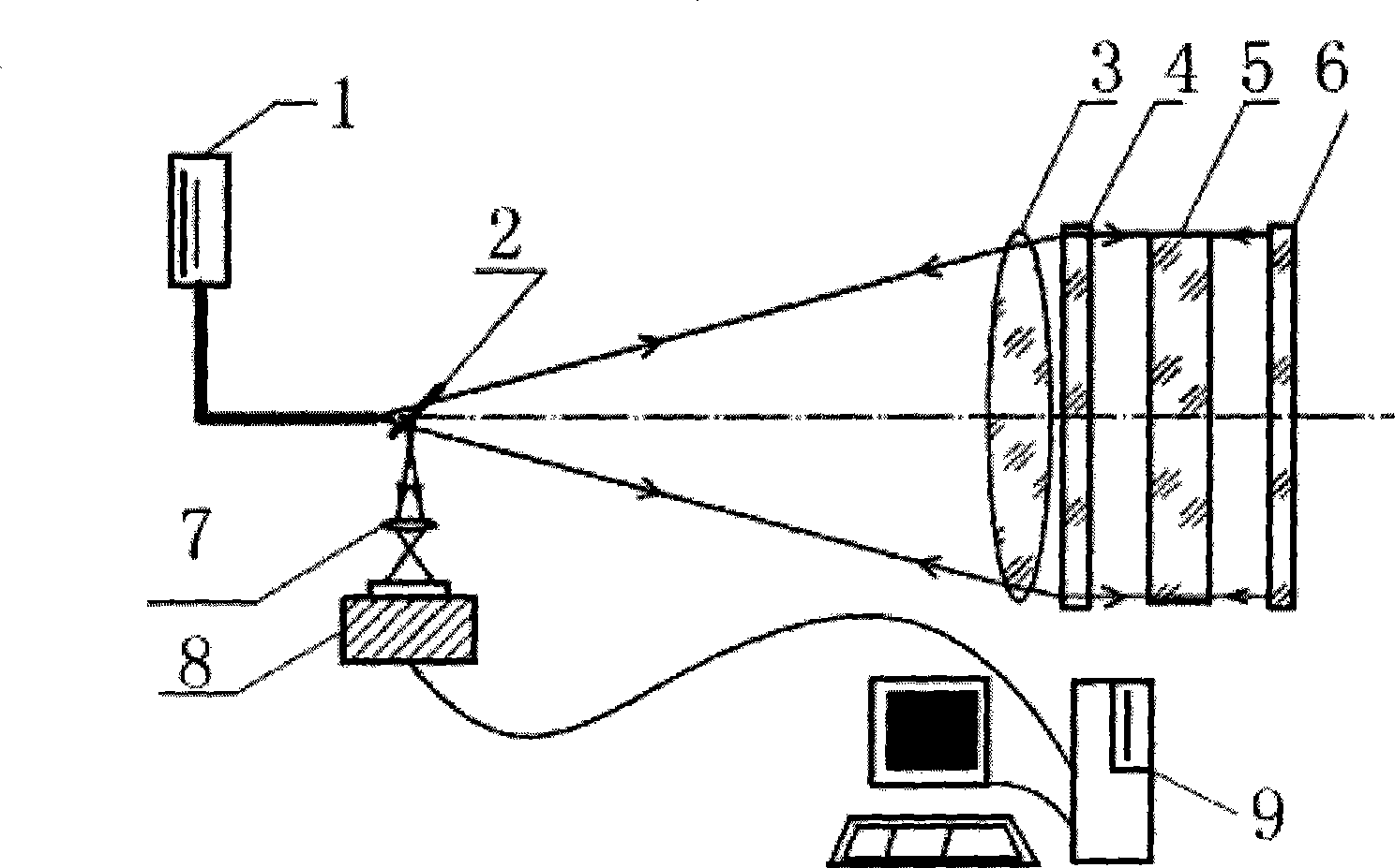
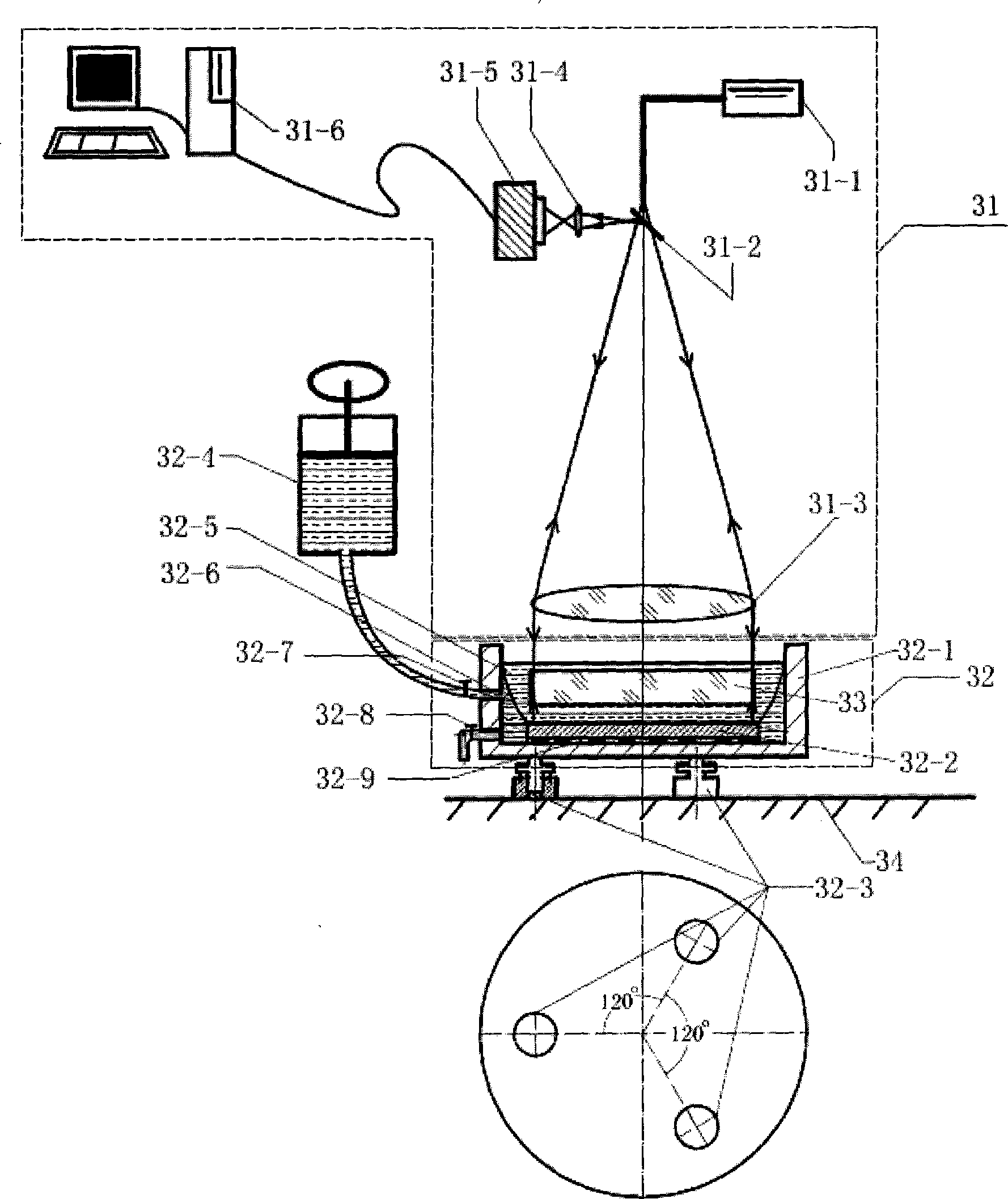
[0043] See first image 3 , image 3 It is a schematic diagram of the optical glass uniformity test device of the present invention. It can be seen from the figure that the testing device for the uniformity of optical glass of the present invention includes:

[0044] The interferometer and data acquisition system 31 consists of a laser 31-1, a beam splitter 31-2, a beam expander objective lens 31-3, an imaging objective lens 31-4, a CCD camera 31-5 and an image acquisition processor 31-6. The positional relationship is: the laser beam emitted by the laser 31-1 passes through the beam splitter 31-2, is collimated by the beam expander lens 31-3, and irradiates the optical glass 33 to be measured in the liquid tank 32-1. The beam expander objective lens 31-3 collects the reflected light beam from the direction of the liquid tank 32-1 and is reflected by the beam splitter 31-2, which is imaged by the imaging objective lens 31-4, captured by the CCD camera 31-5 and sent to the image co...


PUM


Abstract

The invention relates to an optical glass evenness testing device and a test method thereof. The testing device comprises a data acquisition system for an interferometer and a recombined system for a piece of optical glass to be tested, wherein, the interferometer and the data acquisition system consist of a laser, a beam splitter, an extender object lens, an imaging object lens, a CCD camera and an image acquisition processor; the recombined system for the optical glass to be tested comprises a flume; a bearing plate, a granite surface plate, a lifting net and the optical glass to be tested are arranged inside the flume in turn; the flume is provided with an exhaust valve and an injection valve, filled with refractive index matching liquid, communicated with a fluid reservoir which is provided with the refractive index matching liquid through a pipe and the injection valve, and is arranged on a tilt adjustment mechanism which is arranged on a shock-proof platform. The optical glass evenness testing device can directly measure the evenness of the optical glass the surface of which is not preprocessed, is absolute measurement of the refractive index evenness of the optical glass, and can reach the precision of 4x10<-7>.

Description

Technical field [0001] The invention relates to optical glass, in particular to an optical glass uniformity test device and a test method thereof, and is particularly suitable for the uniformity test of large-size and high-precision optical glass materials. Background technique [0002] In recent years, large-energy and high-power laser devices used for laser confinement fusion have developed rapidly, such as NIF in the United States and "Shenguang" in China. These laser devices require a large number of large-size (0.5 to 1m diagonal) flat-type transmission lasers. Optical element. The laser system generally requires 0.25~0.1λ (P-V value) for the transmission wavefront error of this type of optical element. To process such high-precision optical components, on the one hand, the requirements for the optical uniformity of the material are very high, because the thickness of the glass material is 40mm, the local refractive index changes in the order of 10-6, and the distortion caus...

Claims


Application Information

Patent Timeline
IPC IPC(8): G01N21/958
Inventor 张宝安朱宝钤
Owner SHANGHAI INST OF OPTICS & FINE MECHANICS CHINESE ACAD OF SCI
Why Eureka
Try Eureka