
Humidifying tower tail structure

A humidification tower and screw conveyor technology, applied in the direction of solid separation, chemical instruments and methods, electrostatic effect separation, etc., can solve the problems of low dust collection efficiency of humidification tower, high connection equipment height, high outlet flue gas temperature, etc. Achieve the effect of facilitating the overall layout, increasing the residence time and reducing investment

Active Publication Date: 2011-02-02
NANJING XIPU CEMENT ENG GROUP
View PDF0 Cites 0 Cited by
  • Summary
  • Abstract
  • Description
  • Claims
  • Application Information

AI Technical Summary

Problems solved by technology

[0004] The invention solves the problems of low dust collection efficiency of the humidifying tower, easy occurrence of wet bottom, high outlet flue gas temperature, easy blockage of materials, and high height of connecting equipment

Method used


Image

  • Humidifying tower tail structure
  • Humidifying tower tail structure
  • Humidifying tower tail structure

Examples


Embodiment Construction

[0012] The present invention will be further described below in conjunction with accompanying drawing:

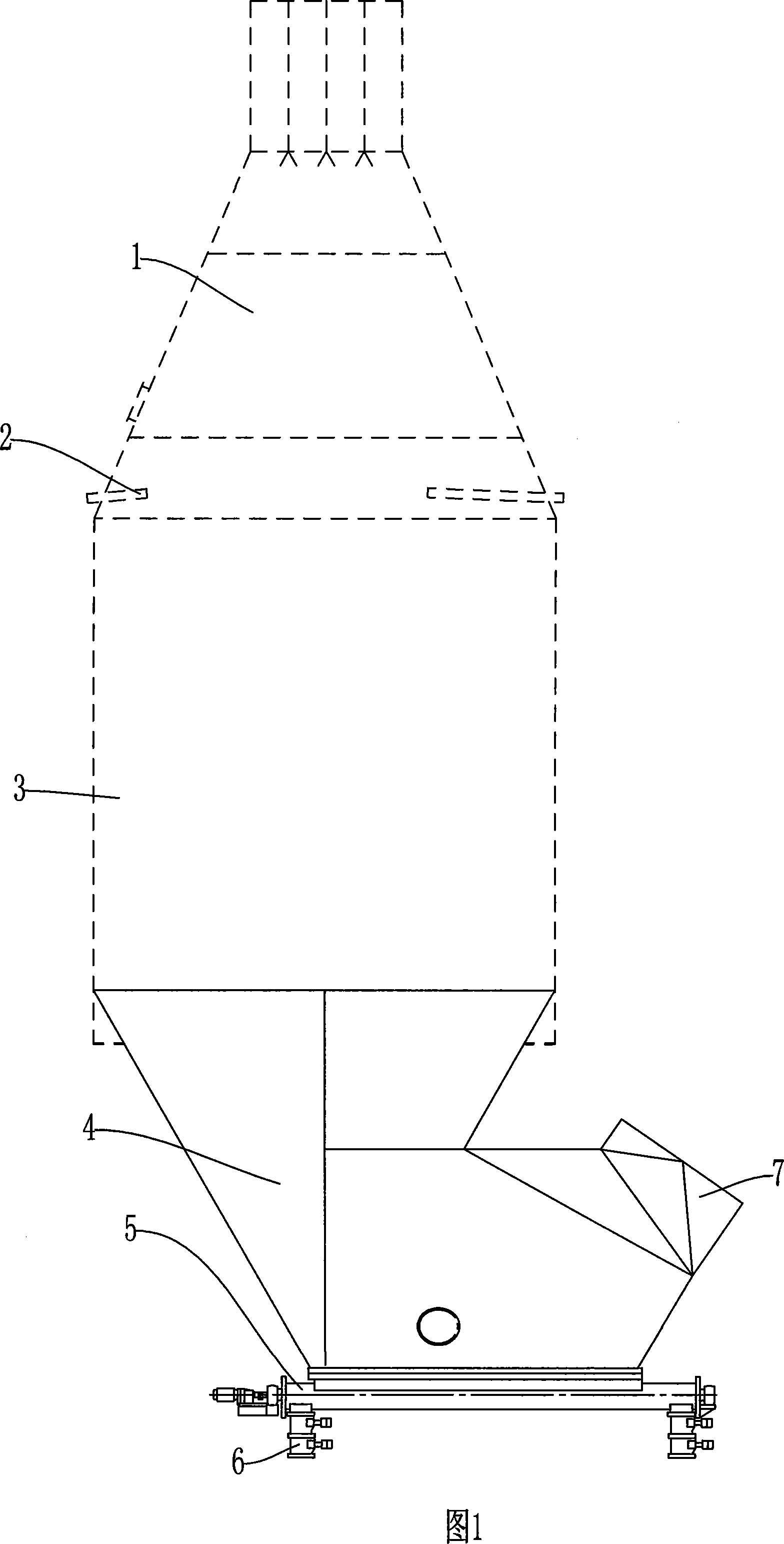
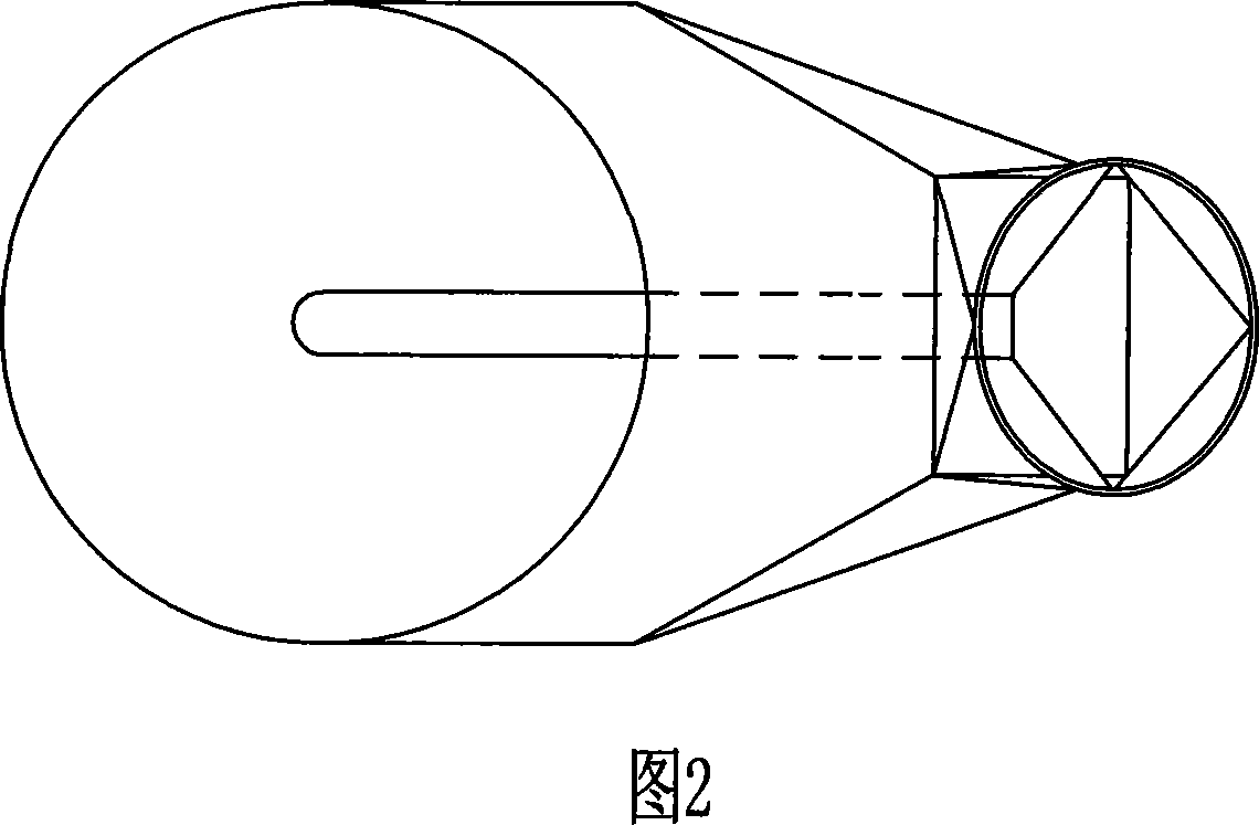
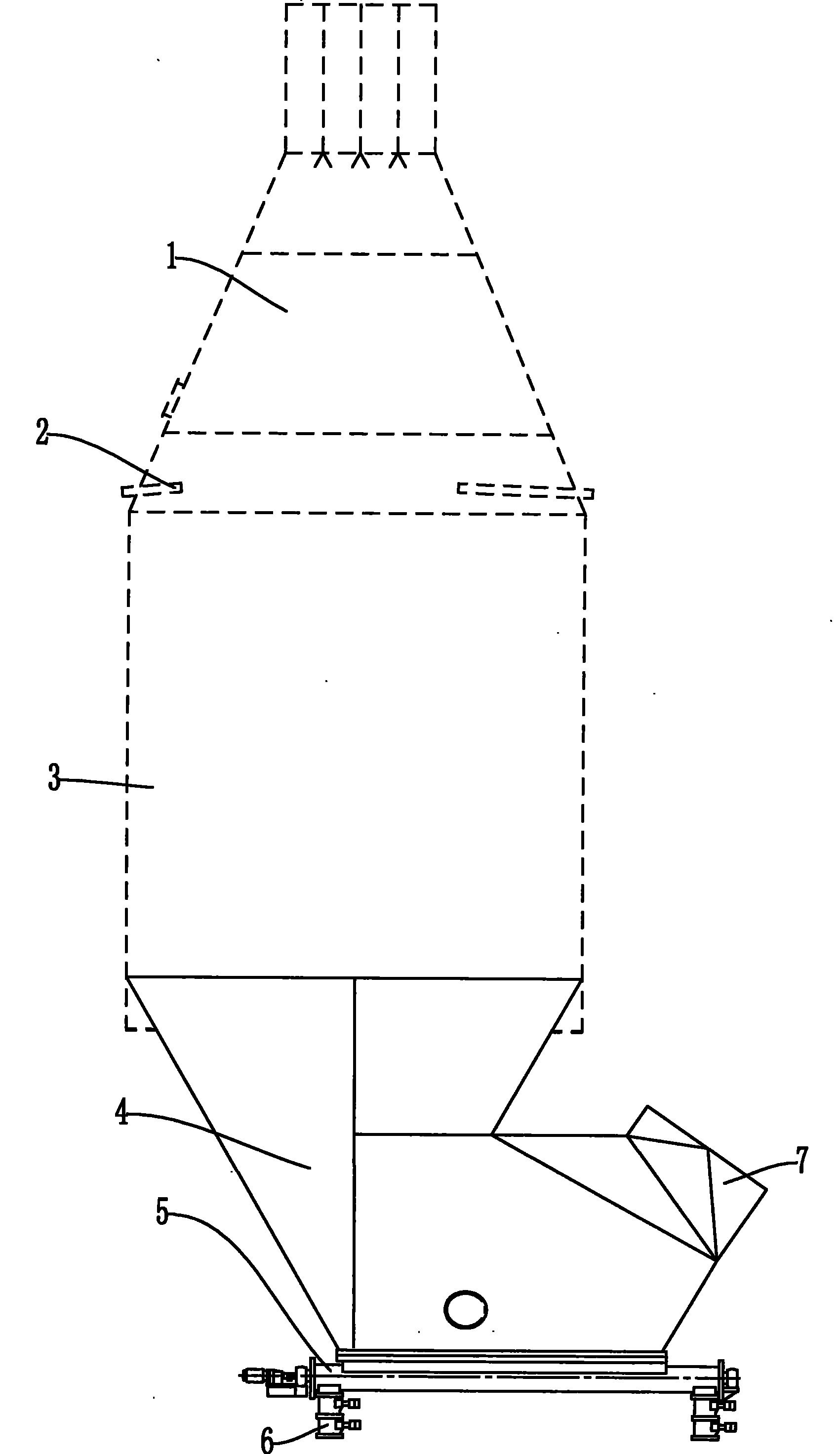
[0013] figure 1 , 2 Among them, the tail device 4 of the humidifying tower is in the shape of a boat (i.e. the boat-shaped tail), the screw conveyor 5 is arranged on the bottom of the ship, one side of the bottom of the ship is basically on the axis of the humidifying tower, and the outlet 7 is arranged on the side of the ship on the other side of the boat-shaped device . The humidification tower includes a tower body 3, one side of the tail device 4 of the humidification tower is connected to the lower part of the tower body 3, the upper part of the tower body 3 is connected to a water spray system 2, and the upper part of the water spray system 2 is connected to the air inlet 1. The air inlet 1 is an inverted cone with a slope, and a porous gas distribution plate is installed inside to improve the air distribution condition. The screw conveyor 5 is moved from directly ...


PUM


Abstract

The invention solves the problems of the prior humidifying tower, such as low dust-collection efficiency, high risk of the bottom wet, high outlet gas temperature, material blockage and large height of the connection equipment. The invention provides a tail portion structure of the humidifying tower which comprises a spiral conveyer arranged at the bottom of the tail structure and an outlet provided on the tail portion. The tail portion structure is ship-shaped and the spiral conveyer is positioned at the bottom of the ship. One side of the ship bottom is substantially positioned on the axialline of the humidifying tower. The outlet is positioned in the broad portion at the other side of the ship-shaped tail structure.

Description

[0001] Technology area [0002] The invention relates to a humidifying tower for humidifying and reducing dust of high-temperature dust-containing gas in building materials and electric power industries. Background technique [0003] The main function of the humidification tower in the process of the cement plant is to humidify the waste gas at the tail of the dry kiln, reduce the specific resistance of high-temperature dust in the waste gas, and improve the working efficiency of the electric dust collector at the tail of the kiln. The tail device under the humidification tower is generally tapered. The screw conveyor is set at the bottom of the cone-shaped device. Due to the action of gravity and the adsorption of water particles, a large amount of dust will settle to the lower cone of the humidification tower. Since the screw conveyor is arranged directly below the humidification tower, and the interface directly below the humidification tower is connected to the interface ...

Claims


Application Information

Patent Timeline
Patent Type & Authority Patents(China)
IPC IPC(8): B03C3/014
Inventor 杨世宏王玉荣周建铭苑明华
Owner NANJING XIPU CEMENT ENG GROUP
Learn More