Control system and control method of vehicular drive system

A control system and vehicle drive technology, applied in electric braking systems, traction and control devices driven by engines, etc., can solve the problems of increasing the amount of work done by the output shaft, increasing the speed change shock, and increasing the inertial force. The effect of reducing the amount of work, reducing the impact of shifting, and easy to change

Inactive Publication Date: 2008-09-03
TOYOTA JIDOSHA KK
View PDF1 Cites 20 Cited by
  • Summary
  • Abstract
  • Description
  • Claims
  • Application Information

AI Technical Summary

Problems solved by technology

For example, if regeneration is performed by the second motor at this time, the amount of work required to raise the output shaft speed increases by an amount corresponding to the regenerative torque of the second motor, in ot

Method used


Image

  • Control system and control method of vehicular drive system
  • Control system and control method of vehicular drive system
  • Control system and control method of vehicular drive system

Examples


Embodiment Construction

[0039] Hereinafter, an exemplary embodiment according to the present invention will be described in detail with reference to the accompanying drawings.

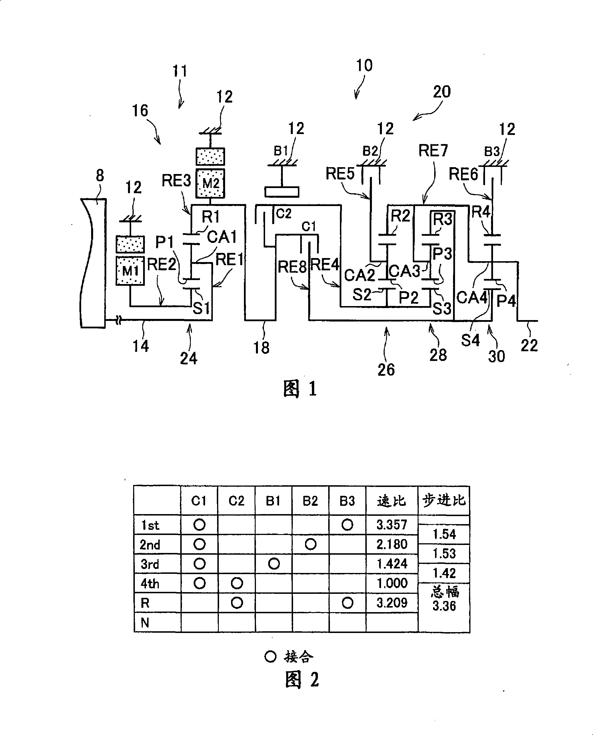
[0040] FIG. 1 is a schematic diagram for explaining a transmission mechanism 10 as a part of a drive system of a hybrid vehicle. In FIG. 1, the transmission mechanism 10 includes the following components arranged in series on a common axis in a transmission housing 12 (hereinafter simply referred to as the housing 12): an input shaft 14 as an input rotating member, a differential operating as a continuously variable transmission The speed unit 11, the automatic transmission 20 as a power transmission unit, and the output shaft 22 as an output rotating member, the housing 12 as a non-rotating or stationary member attached to the vehicle body. The differential unit 11 is directly connected to the input shaft 14 or indirectly connected to the input shaft 14 via a pulsation absorbing damper (vibration damping device) (not shown)....


PUM


Abstract

The present invention provides a control system of vehicle driving system, and control method. The control system of a vehicular drive system is provided with a controller that reduces regeneration torque of a second motor when an automatic transmission that is shifted down during coasting is in an inertia phase. By reducing the regenerating torque of the second motor during the inertia phase, the amount of work required for producing regeneration torque of the second motor is reduced, and the rotational speed of a power transmitting member coupled to a differential unit can be easily raised, whereby shift shock at the time of shifting is favorably reduced.

Description

technical field [0001] The present invention relates to a control system and a control method for a vehicle drive system, the vehicle drive system including an engine, an electric differential unit, a transmission unit and a second electric motor, in which the electric differential unit is controlled to allow a power transmission manner to be different from a differential The operating state of the first electric motor connected to the rotating element of the speed mechanism to control the differential state between the rotational speed of the input shaft and the rotational speed of the output shaft connected to the engine in a way that allows power transmission, the speed change unit and The second electric motor is connected to a power transmission path from the electric differential unit to drive wheels. In particular, the present invention relates to reducing the shift shock that occurs when coasting downshifts during regenerative travel of the vehicle. Background techni...

Claims


Application Information

Patent Timeline
IPC IPC(8): B60W10/02B60W10/08B60W10/10B60K6/445B60K6/547B60L7/26B60L50/16B60W10/18B60W20/00
CPCB60L2240/423Y02T10/6239Y02T10/6286B60W2510/1045B60W30/18072B60K6/547B60L2240/486F16H2037/0873B60W2710/083B60K6/365B60K6/445B60W20/00B60W10/06Y02T10/642B60W30/19B60K6/40B60W10/08B60L50/16Y02T10/62Y02T10/64Y02T10/60Y02T10/7072B60W2710/1011B60W20/30B60W10/12B60W10/10B60W2710/1038Y02T10/70
Inventor 柴田宽之松原亨田端淳
Owner TOYOTA JIDOSHA KK
Why Eureka
Try Eureka