Hydraulically driven and controlled stage hanger rod system

A control system and boom technology, used in portable lifting devices, entertainment devices, entertainment and other directions, can solve problems such as easy vibration damage to machinery, decreasing driving torque, complex transmission system, etc., to achieve stable work, large output torque, controllable high precision effect

Inactive Publication Date: 2008-09-03
LANZHOU UNIVERSITY OF TECHNOLOGY
View PDF0 Cites 6 Cited by
  • Summary
  • Abstract
  • Description
  • Claims
  • Application Information

AI Technical Summary

Problems solved by technology

The traditional boom is generally an electric boom. When the electric boom is running, because the running speed of the AC motor is constant, it is not easy to adjust the speed; when the motor is started, an inrush current is generated, which increases the system load and is prone to vibration. Damage the machinery, increase the error, and generate positioning errors; therefore, an external frequency converter is required; the mechanical transmission system used in the existing stage mechanical boom system uses a frequency converter to realize the stepless speed change of the AC motor to adjust the speed of the boom. The frequency converter is used in this kind of system, the range of speed regulation is not enough, and at the same time, the driving torque decreases gradually. In addition, a mechanical reducer is required to maintain the driving torque, resulting in inconvenient speed regulation, complex transmission system and large positioning error, and there are vulnerable parts. , easy to vibrate and damage machinery, etc. In addition, the transmission system of the existing boom device is relatively complicated

Method used


Image

  • Hydraulically driven and controlled stage hanger rod system
  • Hydraulically driven and controlled stage hanger rod system
  • Hydraulically driven and controlled stage hanger rod system

Examples


Embodiment Construction

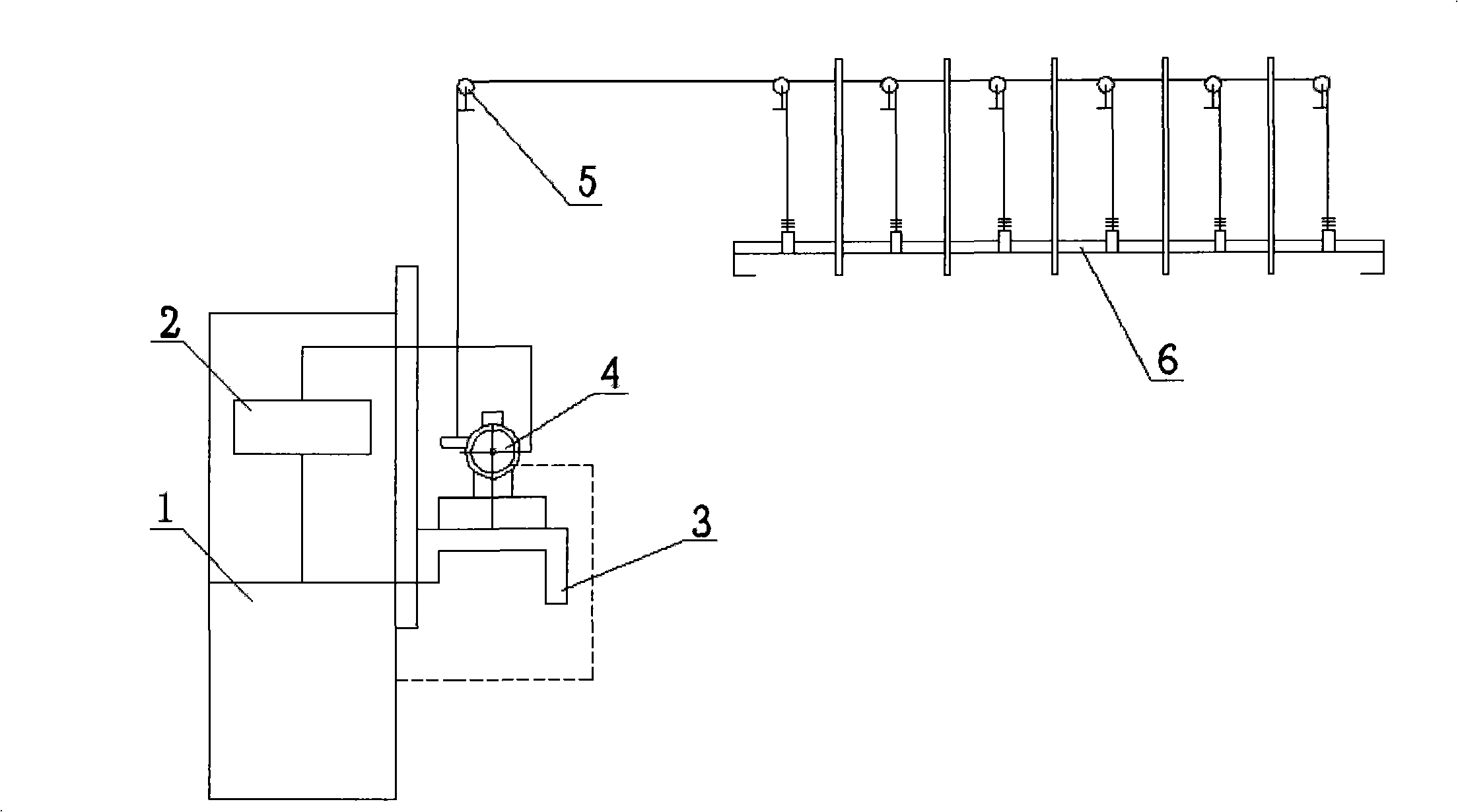
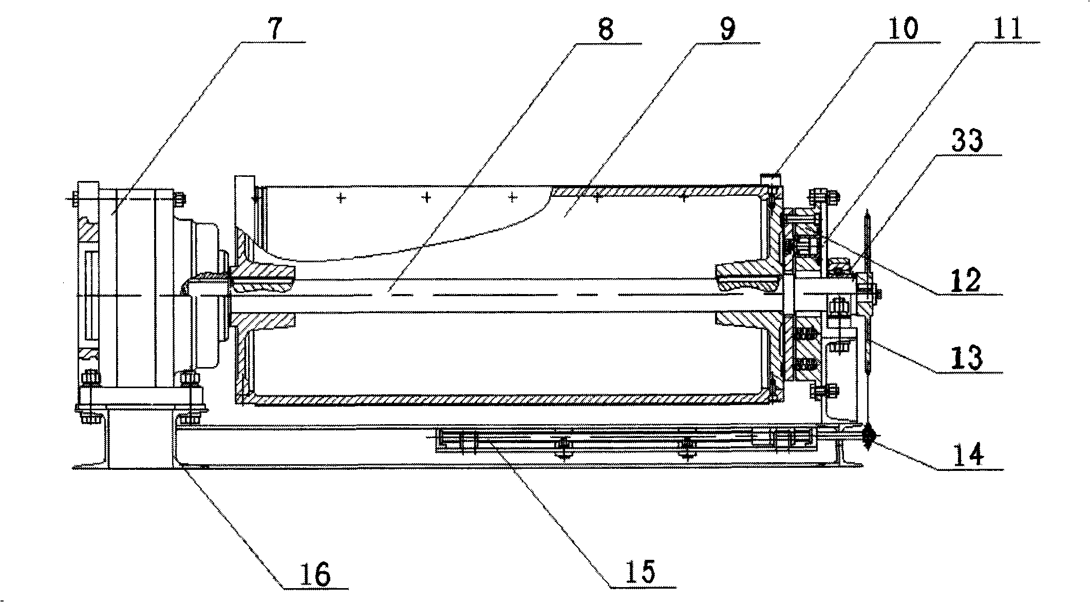
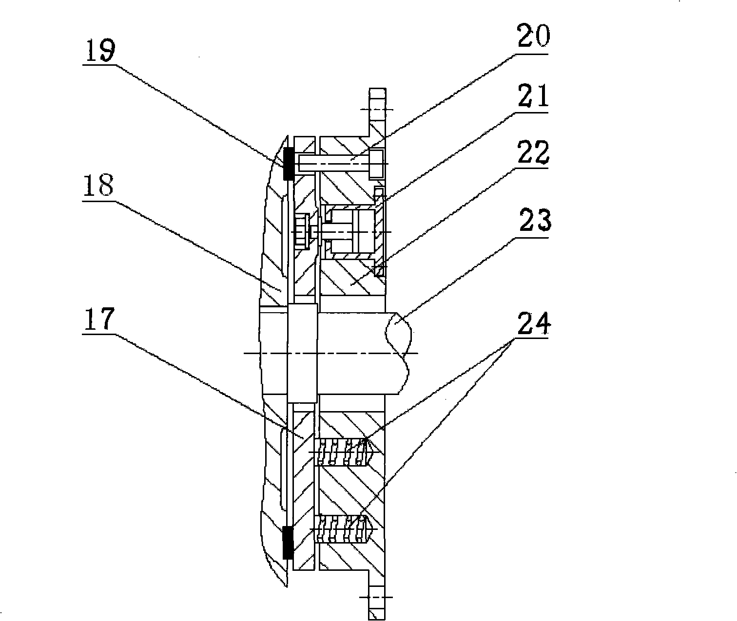
[0019] Such as figure 1 , 2 , 3, and 4, the described a hydraulically driven and controlled stage boom system includes a pulley system 5, a boom 6 and a driving machine 4 arranged on the flyover 3, the present invention is characterized in that: Said flyover 3 is provided with a pumping station 1 and a control system 2 connected with the driving machine 4, the driving machine 4 includes a base 16, the base 16 is provided with a hydraulic motor 7, and one end of the transmission shaft 8 is connected to the power of the hydraulic motor 7. The output ends are connected, the drum 9 is installed on the transmission shaft 8, and the position holder 10 is arranged on the drum 9; the other end of the transmission shaft 8 is installed on the bracket 11 at the end of the base 16 through the outer spherical ball bearing 33 with a seat, and the bracket 11 is provided with a hydraulic brake 12 at the position corresponding to the end face of the drum 9, and the end of the drive shaft 8 ex...


PUM


Abstract

A hydraulically driven and controlled stage suspender system comprises a pulley system (5); a suspender (6); and a driver (4) disposed on an overbridge (3), wherein a pump station (1) and a control system (2) connected with the driver (4) are disposed on the overbridge (3); the driver (4) comprises a pedestal (16); a hydraulic motor (7) is disposed on the pedestal (16); one end of a transmission shaft (8) is connected with the dynamic output terminal of the hydraulic motor (7); a roll (9) is disposed on the transmission shaft (8); a position retainer (10) is disposed on the roll (9); the other end of the transmission shaft (8) is disposed on a support (11) on the end of pedestal (16) through an insert bearing with housing (33); a hydraulic brake (12) is disposed at a position on the support (11) corresponding to the end surface of the roll; and a proportional lead screw (15) is disposed on the pedestal (16). The stage suspender system has the advantages of convenient control, reliability and high efficiency.

Description

technical field [0001] The invention belongs to the technical field of stage machinery equipment, and in particular relates to a stage suspender system driven and controlled by hydraulic pressure. Background technique [0002] The boom device in stage machinery is an important part of stage equipment. Many performance appliances such as scenery and lamps must use the boom to reflect their artistic effects. Through the lifting of the boom, the stage background can be changed and the stage can be enriched. Expressive technique, improve artistic appeal. The traditional boom is generally an electric boom. When the electric boom is running, because the running speed of the AC motor is constant, it is not easy to adjust the speed; when the motor is started, an inrush current is generated, which increases the system load and is prone to vibration. Damage the machinery, increase the error, and generate positioning errors; therefore, an external frequency converter is required; the ...

Claims


Application Information

Patent Timeline
Patent Type & Authority Applications(China)
IPC IPC(8): B66D3/06A63G5/00
Inventor 高文元胡赤兵邬再新张瑾王帆褚金祝振敏井明波
Owner LANZHOU UNIVERSITY OF TECHNOLOGY
Why Eureka
Try Eureka