Wet vapor level suction dehumidifier for steam turbine

A dehumidification device and steam turbine technology, which is applied in mechanical equipment, engine components, machines/engines, etc., can solve problems such as high steam humidity, corrosion of moving blades, and reduced steam power efficiency, so as to slow down the corrosion rate and improve operation safety. , the effect of eliminating hazards

Inactive Publication Date: 2008-09-03
XI AN JIAOTONG UNIV
View PDF0 Cites 6 Cited by
  • Summary
  • Abstract
  • Description
  • Claims
  • Application Information

AI Technical Summary

Problems solved by technology

[0002] The last stages of high-power steam turbines and most stages of nuclear power steam turbines work in the state of wet steam. Wet steam not only reduces the aerodynamic efficiency of their wet steam stages, but also causes the corresponding moving blades to be continuously impacted by high-speed liquid droplets, resulting in Corrosion and even fracture of moving blades
The existing wet steam dehumidifi

Method used


Image

  • Wet vapor level suction dehumidifier for steam turbine
  • Wet vapor level suction dehumidifier for steam turbine
  • Wet vapor level suction dehumidifier for steam turbine

Examples


Embodiment Construction

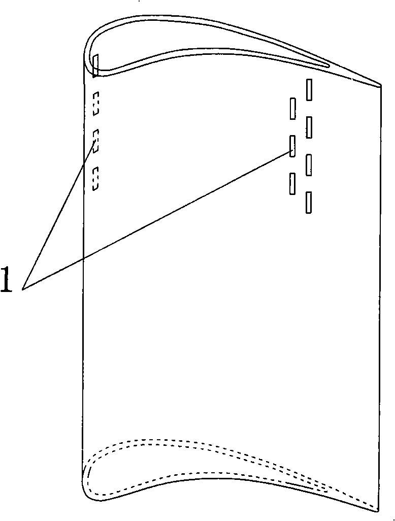
[0018] refer to figure 1 , the inner arc surface and the back arc surface of the stator blade are provided with a suction gap 1, the suction gap of the inner arc surface of the stator blade is set in the rear area of ​​the inner arc surface of the upper half, and the suction gap is two adjacent vertical columns. Open to the strip; the suction slot on the back arc of the stationary blade is set in the front area of ​​the upper half of the back arc, and the suction slot is a row of vertical strip openings. Since the liquid film or stream on the surface of the vane flows upward through the centrifugal action of the vane steam, the lower half of the vane surface accumulates relatively less liquid, so the lower half of the vane surface does not need to open a suction gap.

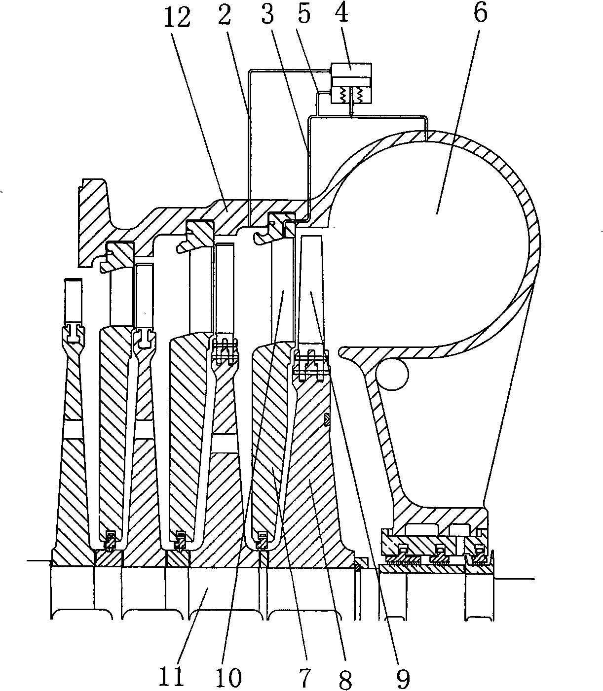
[0019] see figure 2 , the wet steam stage in this embodiment selects the last stage of the steam turbine for illustration. A main shaft 11 is arranged at the center of the cylinder 12 of the steam turbine, an...


PUM


Abstract

The present invention relates to field of steam turbine, discloses a wet steam turbine pump dehumidification device, which comprises a wet steam stage stationary blade of turbine and a last stage discharge volume, the intrados and back arc surface of the stationary blade have a pump gap, the last stage discharge volume and the lumen of stationary blade are communicated by a honeycomb duct, when the steam turbine starts to work, the pump gap inlet and the last stage discharge volume produce positive pressure differential, fluid in intrados and back arc surface of stationary blade enter last discharge volume through the pump gap, the stationary blade lumen and the honeycomb duct. The device can eliminate mostly water damaged for guided vane in wet steam stage of turbine, reduce or eliminate water erosion of guided vane, prolong service life of turbine and enhance safety operation capability.

Description

technical field [0001] The invention relates to the field of steam turbines, in particular to a steam turbine wet steam stage suction and dehumidification device. Background technique [0002] The last stages of high-power steam turbines and most stages of nuclear power steam turbines work in the state of wet steam. Wet steam not only reduces the aerodynamic efficiency of their wet steam stages, but also causes the corresponding moving blades to be continuously impacted by high-speed liquid droplets, resulting in Corrosion and even fracture of moving blades. The existing wet steam dehumidification technology is to set up a dehumidification tank on the cylinder near the air inlet of the wet steam stage vane. The structure and manufacturing process of this dehumidification tank are simple, but the dehumidification effect is relatively poor, especially in the back of the steam turbine. In the case of low pressure, the vapor humidity is relatively high, and the dehumidification...

Claims


Application Information

Patent Timeline
IPC IPC(8): F01D25/32
Inventor 戴义平王江峰高林李磊
Owner XI AN JIAOTONG UNIV
Why Eureka
Try Eureka