
System and method for testing concentricity of lens module

A lens module and detection system technology, applied in the direction of lens position determination, measuring device, testing optical performance, etc., can solve the problems of error, slow speed, low efficiency and precision, etc., improve detection efficiency, reduce production cost, save human effect

Inactive Publication Date: 2008-09-03
江门英讯通光电科技有限公司
View PDF0 Cites 14 Cited by
  • Summary
  • Abstract
  • Description
  • Claims
  • Application Information

AI Technical Summary

Problems solved by technology

[0005] However, the usual method of manually rotating the lens barrel is slow, low in efficiency and precision, and due to the influence of human fatigue and mood, it is impossible to guarantee that each manual rotation can achieve the required angle, and sometimes it will cause large error

Method used


Image

  • System and method for testing concentricity of lens module
  • System and method for testing concentricity of lens module
  • System and method for testing concentricity of lens module

Examples


Embodiment Construction

[0013] The present invention will be further described in detail below in conjunction with the accompanying drawings.

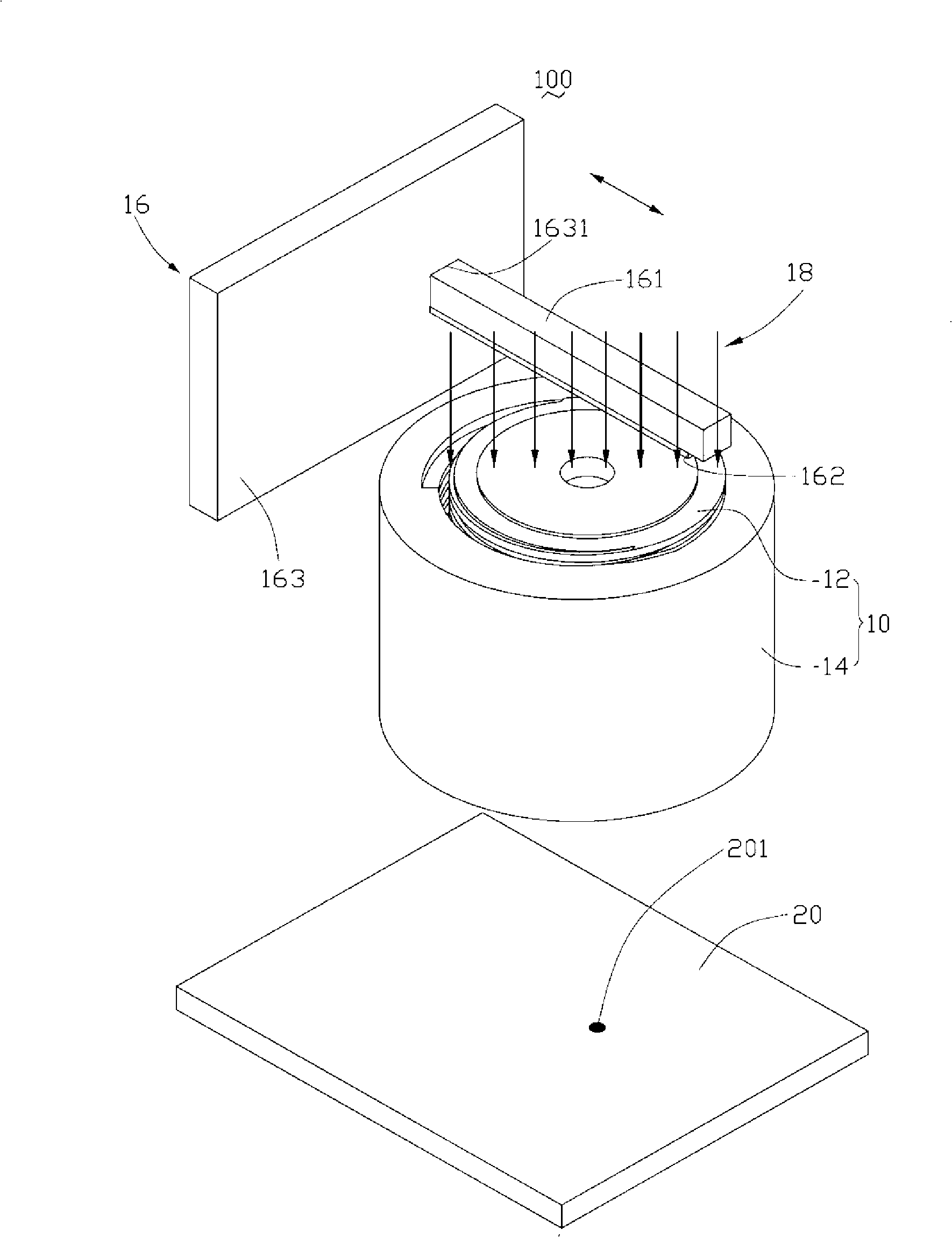
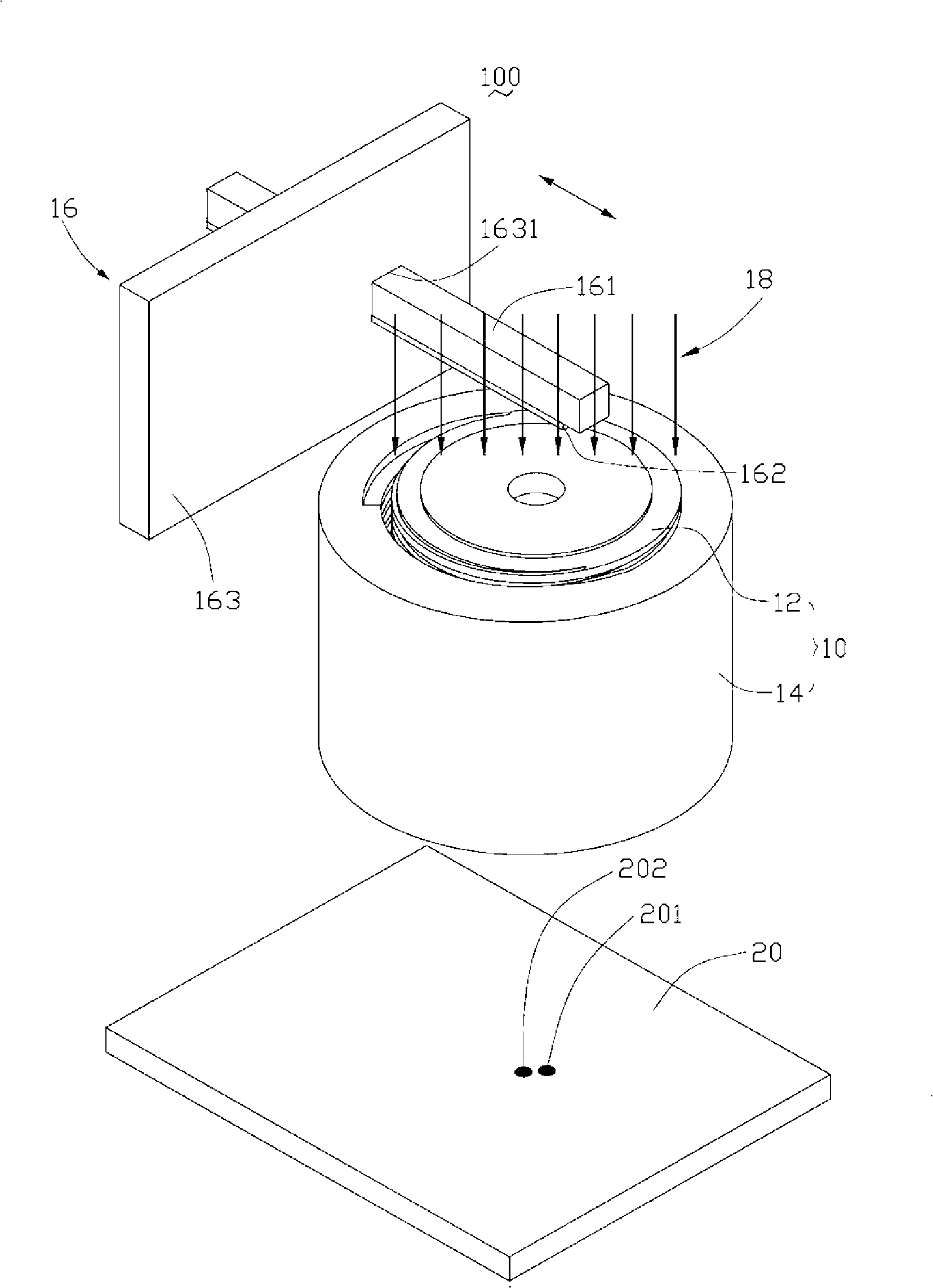
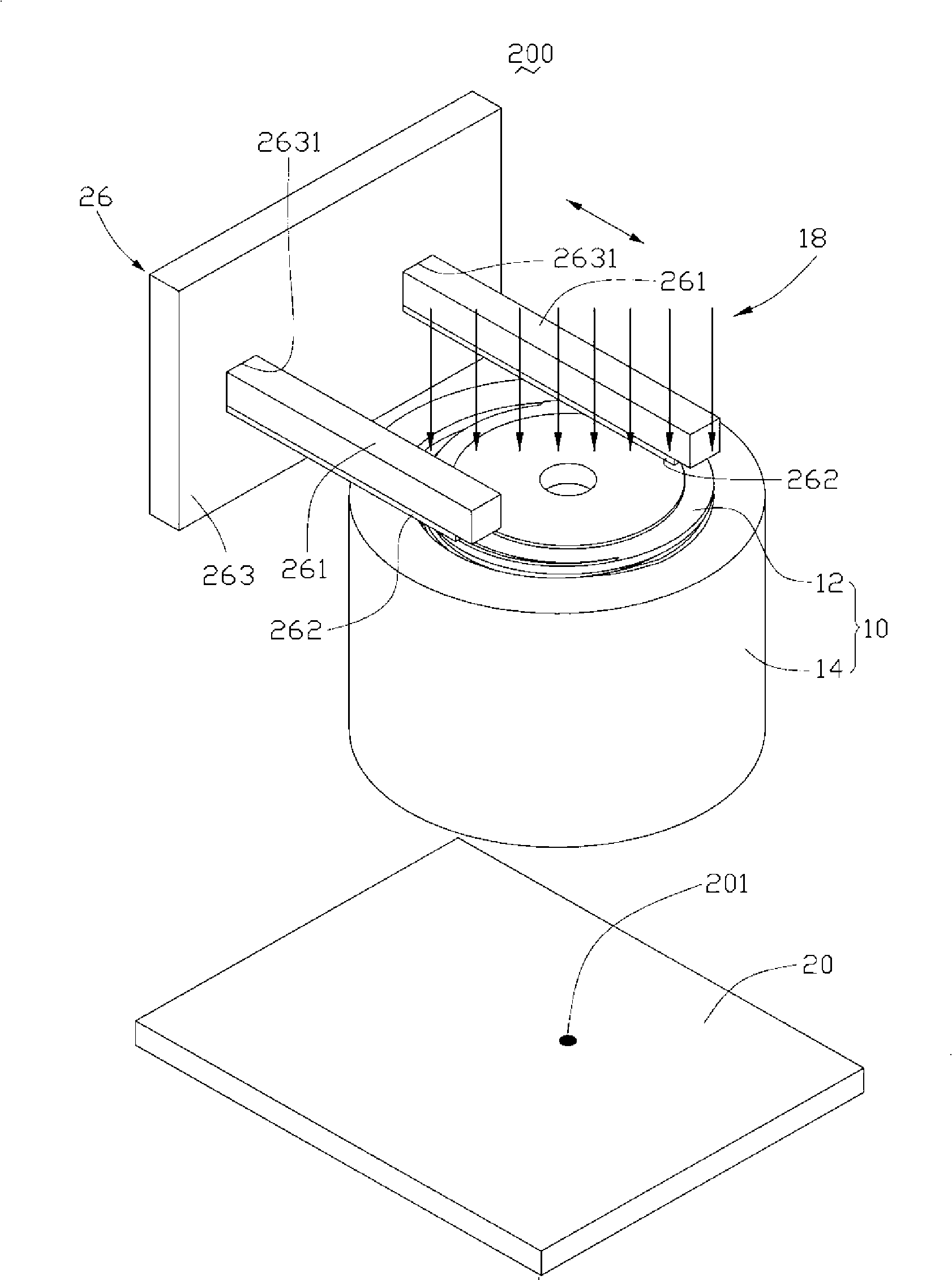
[0014] see figure 1 , is the lens module concentricity detection system 100 according to the first embodiment of the present invention. The lens module concentricity detection system 100 includes a lens barrel rotation driving device 16 , a light source 18 and an optical axis deviation detection device 20 . The detected component in this embodiment is a lens module 10 , which includes a lens barrel 12 and a lens base 14 .

[0015] The lens barrel rotation driving device 16 includes a reciprocating root-type moving rod 161 , a friction block 162 , a moving rod limiting device 163 and a motor (not shown). The reciprocating moving rod 161 is located at one end of the lens module 10 and is in contact with the lens barrel 12 to drive the lens barrel 12 to rotate relative to the lens holder 14. Parameter relationship, specifically, such as the moving length of t...


PUM


Abstract

The invention discloses a system for testing lens module coaxiality, which is used for testing coaxiality between base and column in lens module, including: a light source, a column rotation driving equipment and an optical axis deviation testing equipment. The column rotation driving equipment includes at least one piece of reciprocating type shifting bar, every piece of reciprocating type shifting bar is contacted with the surface of column for driving the column to rotate relative to the base. The reciprocating type shifting bar is used for driving the column to rotate relative to the base for a preset angle, in order to save labour power and reduce producing cost; similarly, using the coaxiality testing method of the lens module coaxiality testing system can improve the efficiency for testing the axial coaxiality between the column and the base. The invention also relates to a lens module coaxiality testing method.

Description

technical field [0001] The invention relates to a lens module concentricity detection system and a detection method thereof, in particular to a detection system with a lens module concentricity detection function and a detection method thereof. Background technique [0002] In recent years, with the development of optical products, the scope of application of lens modules continues to expand, such as digital cameras, mobile phones with camera functions and other electronic products. For electronic products, especially consumer electronic products, the development trend is light weight and thinner, and the corresponding lens modules are getting smaller and smaller, and the precision requirements are getting higher and higher, so the lens The module assembly process also requires higher precision and stability to ensure production efficiency and yield. [0003] Generally, the assembly method of the lens module is to put each optical device into the lens barrel in sequence, su...

Claims


Application Information

Patent Timeline
Patent Type & Authority Applications(China)
IPC IPC(8): G01M11/02G01B11/27
CPCG02B27/62G01M11/0221G01B11/27G01B11/03
Inventor 颜士杰
Owner 江门英讯通光电科技有限公司
Learn More