Error correction device and recording and reproducing device

A technology of error correction and equipment, applied in digital recording/reproduction, digital signal error detection/correction, data recording, etc., can solve the problem of large area of ​​buffer capacity error correction circuit, and achieve the effect of reducing buffer capacity

Inactive Publication Date: 2008-09-03
RENESAS ELECTRONICS CORP
View PDF1 Cites 2 Cited by
  • Summary
  • Abstract
  • Description
  • Claims
  • Application Information

AI Technical Summary

Problems solved by technology

In the error correction circuit of the background art, the buffer capacity required for the error correction process and the area of ​​the error correction circuit are large

Method used


Image

  • Error correction device and recording and reproducing device
  • Error correction device and recording and reproducing device
  • Error correction device and recording and reproducing device

Examples


no. 1 example

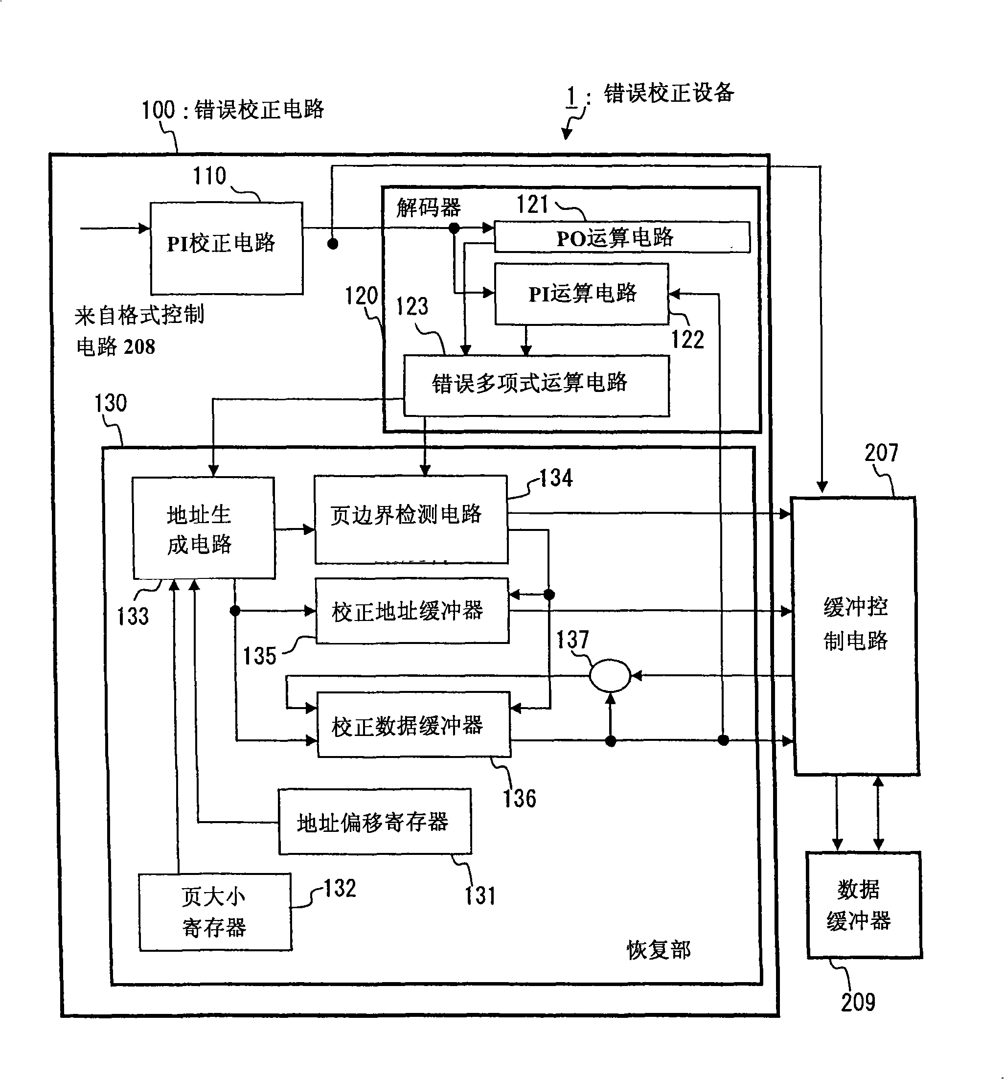
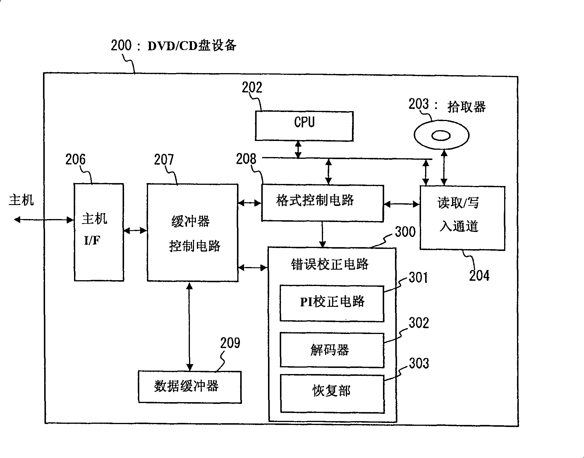
[0051] figure 1 is a block diagram of a configuration example of the error correction circuit according to the first embodiment of the present invention. Such as figure 1 The error correction circuit (error correction section) 100 shown in the image 3 The DVD / CD disc device (recording and reproducing device) 200 shown functions in a device constructed in the same manner. The error correction circuit 100 may be used instead of the error correction circuit 300 included in the DVD / CD disc device 200 . figure 1 The error correction circuit 100 shown in includes a PI correction circuit 110, a decoder (decoding section) 120 and a restoration section (reconstruction section) 130, which can be used to replace the image 3 The PI correction circuit 301, the decoder 302 and the restoration part 307 shown in . even when figure 1 When the shown error correction circuit 100 is mounted on a DVD / CD disc device 200, image 3 The operation of the DVD / CD disc device shown in is also the...

no. 2 example

[0084] In the second embodiment, a case where a disk of HD DVD (High Definition DVD) is read out in a disk device will be described. The system structure is the same as that of the first embodiment. Therefore, repeated descriptions are omitted.

[0085] The format control circuit 208 processes the data read out from the recording medium (uncorrected data) into data having 364 bytes*208 lines in HD DVD. Data having 364 bytes*208 lines is called an ECC block, and the error correction process of HD DVD is performed in units of this ECC block. The data from the 173rd byte to the 182nd byte of each line and the data from the 355th byte to the 364th byte are called PI, and the data from the 193rd line to the 208th line of each ECC block is called PO . The 20 bytes of each row of each ECC block and the last 16 rows are called ECC codes. The data of 344 bytes*192 lines other than the ECC code is actual data.

[0086] The number of pages required to store 1ECC of data in the data ...


PUM


Abstract

An error correction device is a device detecting and correcting an error of uncorrected data. The error correction device includes a temporary storage buffer (data buffer) having a storage area divided into a plurality of units and storing the uncorrected data divided into storage area units, and an error correction part (error correction circuit) repeatedly performing detecting an error of the uncorrected data stored in the temporary storage buffer, correcting the detected error, and writing the corrected error into the temporary storage buffer for each storage area unit. The error correction part corrects the error of the uncorrected data for storage area unit of the temporary storage buffer to successively write the corrected data into the temporary storage buffer.

Description

technical field [0001] The present invention relates to error correction devices, and more particularly, to error correction devices that store corrected data in a data buffer composed of a plurality of storage areas. Background technique [0002] Due to the Blu-ray standard and the HD DVD (High Definition Digital Versatile Disc) standard, the development of recording media with high capacity has recently been accelerated. In some DVD disc devices, a large amount of data needs to be processed at high speed. For example, in image 3 and 4 A structure in which the technology disclosed in Japanese Unexamined Patent Application Publication No. 2001-143408 is applied to a DVD / CD (Digital Versatile Disc / Compact Disc) disc device will be shown in . Figure 5 Indicates the data format of ECC (Error Checking and Correction) of DVD. [0003] image 3 It is a block diagram showing an example of the overall configuration of a DVD / CD disc device according to the background art. Herei...

Claims


Application Information

Patent Timeline
IPC IPC(8): G11B20/18
CPCG11B2020/1836H03M13/2909G11B2220/2579G11B20/10527H03M13/2948G11B2220/2562G11B2020/1062H03M13/2927G11B2220/63G11B2020/1853G11B20/1833H03M13/151
Inventor 门松辉洋
Owner RENESAS ELECTRONICS CORP
Why Eureka
Try Eureka