Method and apparatus for forming of radiation orientating round ring-shaped magnetic body

A technology of radiation orientation and forming method, applied in the manufacture of permanent magnets, inductors/transformers/magnets, electrical components, etc., can solve the problems of low degree of orientation, high degree of orientation, uneven degree of orientation, etc., and achieve the effect of complete orientation

Active Publication Date: 2011-06-29
SHENZHEN RADIMAG TECH CO LTD
View PDF0 Cites 1 Cited by
  • Summary
  • Abstract
  • Description
  • Claims
  • Application Information

AI Technical Summary

Problems solved by technology

The biggest disadvantage of this method is that the degree of orientation is not uniform, some parts have high degree of orientation, and some parts have low degree of orientation
This method improves the uniformity of the orientation magnetic field to a certain extent. The biggest disadvantage is that when the inner diameter of the radiation ring is small, the intensity of the orientation magnetic field will be greatly reduced, so that the orientation of the magnetic powder is not complete (the first orientation method also has similar defects) , when the height of the radiation ring is high, not only the intensity of the orientation magnetic field weakens but also the uniformity becomes worse, all of which make the magnetic properties and consistency of the radiation ring worse

Method used


Image

  • Method and apparatus for forming of radiation orientating round ring-shaped magnetic body
  • Method and apparatus for forming of radiation orientating round ring-shaped magnetic body
  • Method and apparatus for forming of radiation orientating round ring-shaped magnetic body

Examples


Embodiment 1

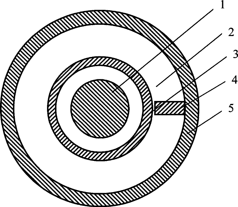
[0020] Embodiment 1: Make a radiation ring with an inner magnetic pole-outer magnetic pole orientation magnetic field.

[0021] Such as figure 1 As shown, when the two poles (N pole and S pole) of the magnetic field generated by the electromagnet or permanent magnet are respectively introduced into the inner magnetic pole 1 and the outer magnetic pole 5 through a certain magnetic conduction device, the inner magnetic pole 1 and the outer magnetic pole gathering head will be 4 to form a strong magnetic field. If the cavity 2 is filled with magnetic powder at this time, the magnetic powder in the magnetic field will be fully magnetized and oriented. If the outer magnetic pole gathering head 4 is fixed on the outer magnetic pole 5, the magnetization and radiation orientation of all the magnetic powder in the mold cavity 2 can be realized by driving the outer magnetic pole 5 to rotate at a high speed. While magnetizing and orienting the magnetic powder in the mold cavity 2, acco...

Embodiment 2

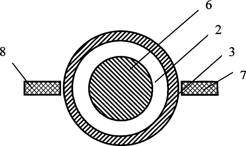
[0022] Embodiment 2: Make radiation ring with outer magnetic pole-outer magnetic pole type orientation magnetic field

[0023] Such as figure 2 As shown, when the two poles (N pole and S pole) of the magnetic field produced by the electromagnet or the permanent magnet are respectively introduced into the first outer magnetic pole 7 and the second outer magnetic pole 8 through a certain magnetic conduction device, it will be in the magnetic permeable core 6 Two strong magnetic fields are simultaneously formed between the first outer magnetic pole 7 and between the magnetic permeable core 6 and the second outer magnetic pole 8 . If the cavity 2 is filled with magnetic powder at this time, the magnetic powder in the two magnetic fields will be fully magnetized and oriented. The magnetization and orientation of all the magnetic powder in the mold cavity 2 can be realized by driving the first outer magnetic pole 7 and the second outer magnetic pole 8 to rotate at high speed at th...

Embodiment 3

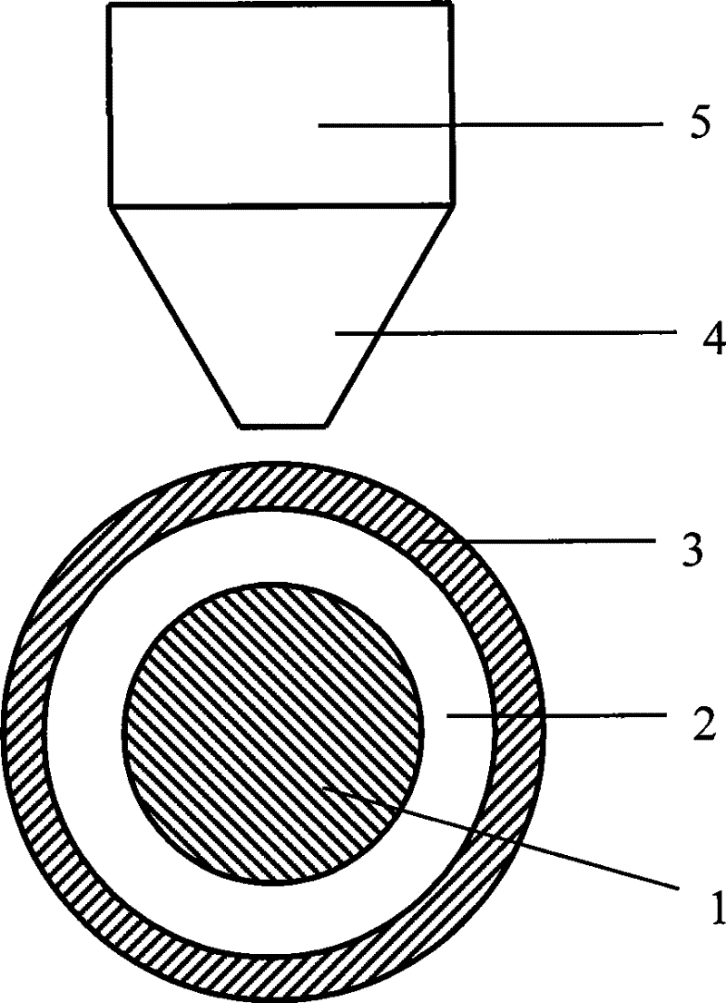
[0024] Embodiment 3: Another method of making a radiation ring with an inner magnetic pole-outer magnetic pole type orientation magnetic field

[0025] Such as image 3As shown, when the two poles (N pole and S pole) of the magnetic field generated by the electromagnet or permanent magnet are respectively introduced into the inner magnetic pole 1 and the outer magnetic pole 5 through a certain magnetic conduction device, the inner magnetic pole 1 and the outer magnetic pole gathering head will be 4 to form a strong magnetic field. If the cavity 2 is filled with magnetic powder at this time, the magnetic powder in the magnetic field will be fully magnetized and oriented. If (1) the magnetic powder in the non-magnetic mold 3 and the mold cavity 2 and the inner magnetic pole 1 are fixed on the frame of the molding equipment and relatively stationary, the outer magnetic pole 5 and the magnetic head 4 are connected to the rotary drive mechanism to surround the non-magnetic mold 3 ...


PUM


Abstract

The present invention discloses a molding method and apparatus for circular ring magnetic body in radiating way to resolve the technical problems which make magnetic powder uniform. Methods of the invention are that: orientation magnetic field is disconnected setting at circular ring magnetic body with 360 degrees in forming process, the forming process has relative rotation movement between orientation magnetic field and magnetic powder; the equipment of the invention is equipped with ring shaped molding chamber in the orientation magnetic field, and the orientation magnetic field is disconnected at circular ring magnetic body with 360 degrees, a moving structure with relative rotation is formed between one magnetic pole and another magnetic pole in orientation magnetic field, or betweenthe ring shaped mold form and the orientation magnetic field, The present invention has more complete orientation to the magnetic powder compared with the present technology, because the orientation magnetic field at 360 degree is same with the magnetic field, the degree of orientation of radiating ring at different angle is identical, so the present invention can be used for producing sintered radiating ring magnetic body, bonding radiating ring magnetic body and bonding injection molding radiating ring magnetic body.

Description

technical field [0001] The invention relates to a manufacturing method and equipment of a radially oriented annular magnetic material, in particular to a forming method and equipment for a radially oriented annular magnet. technical background [0002] A circular magnet oriented radially or radially (referred to as a radial ring) has broad application prospects in the field of motors. The biggest technical difficulty in making the radiation ring is the orientation method of the magnetic powder in the forming (or pressing) stage. At present, there are two main orientation methods used in the magnetic material industry: the first is the segmented orientation method, which divides the ring into several parts, and guides each part into an orientation magnetic field for orientation. The biggest shortcoming of this method is that the degree of orientation is not uniform, some parts have high degree of orientation, and some parts have low degree of orientation. The uneven orienta...

Claims


Application Information

Patent Timeline
Patent Type & Authority Patents(China)
IPC IPC(8): H01F41/02
CPCH01F41/028B22F2999/00B22F3/087B22F5/106B22F2202/00B22F2202/05
Inventor 吴锡军
Owner SHENZHEN RADIMAG TECH CO LTD
Why Eureka
Try Eureka