Earthing rotating plough drilling machine

A drilling rig and drilling box technology, which is applied in the field of soil-cultivation rotary plough drilling rigs, can solve the problems of the rotary plough blade being unable to deeply transmit the ploughed land and being easily affected.

Inactive Publication Date: 2008-09-10
陈则铭
View PDF0 Cites 8 Cited by
  • Summary
  • Abstract
  • Description
  • Claims
  • Application Information

AI Technical Summary

Problems solved by technology

[0002] Most of the agricultural crops in our country use rotary tillers or livestock and manual cultivation. The handrails of existing rotary tillers are generally fixed mechanisms, and there are obvious defects in the rotation adjustment within the range of 360 degrees around the working circle or in the vertical direction. In this way, when the land is cultivated, the land with obstacles on the edge and side is easily affected; the rotary tiller of the existing rotary tiller is generally connected with the rotating structure shaft, and the rotary tiller is installed on the sides of the left and right sides of the reduction box, so that the rotating structure There is a gap in the cultivated land on the front of the reduction box on the shaft. The cultivated land on the front of the reduction box is the working blind spot of the rotary tiller. Since the rotary tiller cannot reach the front of the reduction box, there is a gap in the cultivated land. In this way, the cultivated ground forms a ridge, which is affected Influenced by the resistance of the ridge, the rotary tiller cannot plow the cultivated land deeply during the forward pushing process.

Method used


Image

  • Earthing rotating plough drilling machine
  • Earthing rotating plough drilling machine
  • Earthing rotating plough drilling machine

Examples


Embodiment Construction

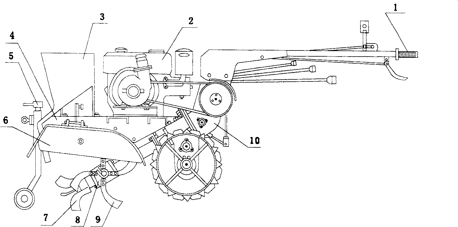
[0019] A rotary plow drilling rig for cultivating soil, comprising a power machine 2 and its power transmission mechanism, a driving wheel and a rotary tillage device. The power machine 2 is arranged on the top of the machine beam 4, a rotary plow drilling box 8 is arranged below the power machine 2, and a universal movable control handle 1 is arranged on the soil-cultivating rotary plow drilling machine, and the rotary tillage device includes a rotary plow drilling box 8 The three-claw leaf drill 7 at the front end and the rotary tiller 9 arranged on both sides of the rotary plow drill case.

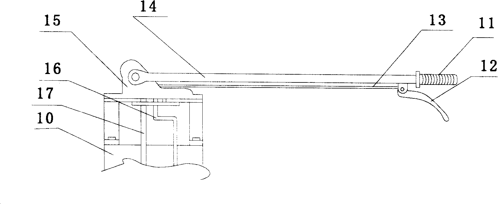
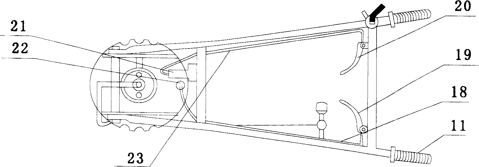
[0020] The universal movable control handle includes a handle 11, an accelerator and clutch control mechanism and a handrail 14. The front end of the handrail 14 is equipped with a turntable 15 connected to the locomotive gearbox 10. A clutch pull rod 17 is arranged in the center of the turntable 15. The clutch There is respectively a steering pull rod 16 on the rotating disk 15 on both...


PUM


Abstract

The invention provides a hilling rotary plough drill which pertains to the technical field of agricultural machinery, comprising an engine, a power transmission mechanism, a driving wheel and a rotary cultivating device. The upper part of the beam of the drill is provided with the engine, a rotary plough drilling box is arranged below the engine, and a universal movable operating handle is arranged on the drill. The rotary cultivating device comprises a three-jaw blade drill which is arranged at the front end of the rotary plough drilling box and rotary blades which are arranged at the two sides of the rotary plough drilling box. The front part of the beam of the hilling rotary plough drill is provided with a depth locater. The beam which is arranged at the upper part of the rotary plough drilling box is provided with a movable mudguard. The hilling rotary plough drill of the invention is convenient to operate and solves the working blind points at the front part of the arable land of a reduction box; furthermore, the three-jaw blade drill of the rotary plough drilling box, the side rotary hilt seats and the side blades of the drill can be assembled or disassembled, thus different plough tools can be assembled according to the requirement.

Description

technical field [0001] The utility model relates to a rotary plow drill for cultivating soil, which belongs to the technical field of agricultural machinery. Background technique [0002] Most of the agricultural crops in our country use rotary tillers or livestock and manual cultivation. The handrails of existing rotary tillers are generally fixed mechanisms, and there are obvious defects in the rotation adjustment within the range of 360 degrees around the working circle or in the vertical direction. In this way, when the land is cultivated, the land with obstacles on the edge and side is easily affected; the rotary tiller of the existing rotary tiller is generally connected with the rotating structure shaft, and the rotary tiller is installed on the sides of the left and right sides of the reduction box, so that the rotating structure There is a gap in the cultivated land on the front of the reduction box on the shaft. The cultivated land on the front of the reduction box...

Claims


Application Information

Patent Timeline
Patent Type & Authority Applications(China)
IPC IPC(8): A01B33/00A01B33/08A01B33/10
Inventor 陈则铭
Owner 陈则铭
Why Eureka
Try Eureka