Water flow mud-sand separating system for drip irrigation

A separation system, water flow sediment technology, applied to the separation method, filtration separation, sediment separation by centrifugal force, etc., can solve the problems that the separation of sediment can not achieve efficiency and effect, can not use drip tanks, etc., to achieve a stable separation effect, The effect of long service life

Inactive Publication Date: 2008-09-10
LANZHOU UNIVERSITY OF TECHNOLOGY +1
View PDF1 Cites 1 Cited by
  • Summary
  • Abstract
  • Description
  • Claims
  • Application Information

AI Technical Summary

Problems solved by technology

For the water flow with large sediment content and small sediment particle size, the separation of sediment by this technology cannot achieve good efficiency and effect, and the treated flowing water containing fine sediment cannot be used in drip tanks

Method used


Image

  • Water flow mud-sand separating system for drip irrigation
  • Water flow mud-sand separating system for drip irrigation

Examples


Embodiment Construction

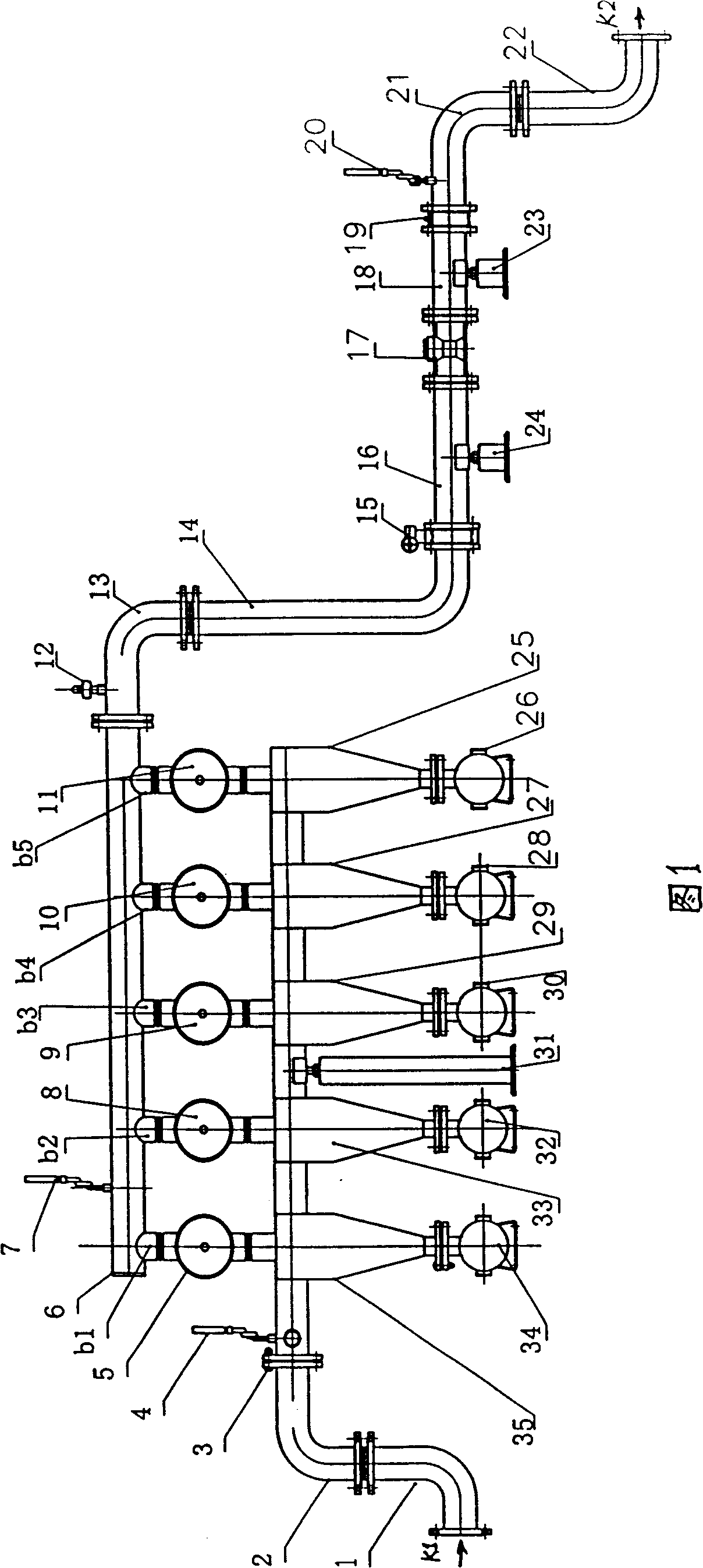
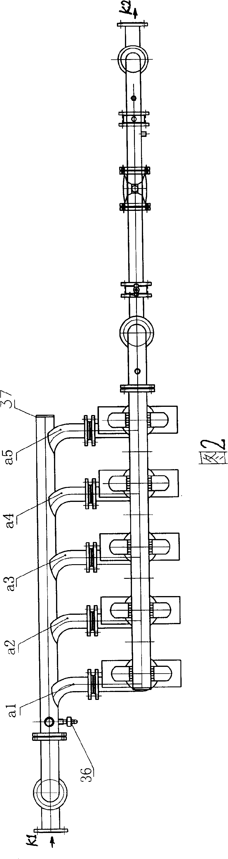
[0008] As shown in Figure 1, the present invention is a kind of water flow sediment separation system that is used for drip irrigation, and the upper part of its cyclone centrifugal separator is a cylinder, and the lower part is a cone, and the sediment outlet at the bottom of the cyclone centrifugal separator is A sand collecting tank is connected, and the water inlet pipe is composed of a first water inlet pipe 1 and a second water inlet pipe 2 . As shown in Figure 2, the second water inlet pipe 2 is connected to the water distribution pipe 37 through the flange 3, and the first water distribution pipe a1, the second distribution pipe a2, and the third water distribution pipe 37 are respectively equipped with five water splitting pipes. The pipe a3, the fourth branch pipe a4, and the fifth branch pipe a5, the water inlet of each branch pipe are installed on the water branch pipe 37 obliquely relative to the flow direction of the water inlet, and the water inlet of the first b...


PUM


Abstract

A flow sediment separation system for dripping irritation aims at improving the sediment separation efficiency of large river flows with greater sediment content. An inlet pipe is connected with distributed pipes which are respectively provided with five water shunts for dividing discharge of stream, The inlet of each water shunt is respectively installed on the distributed water pipes obliquely and accordingly to the direction flow of inlet water, and from the one nearest to the inlet pipe, the cross- sectional areas of the water shunts are 1 / 5, 2 / 5, 3 / 5, 4 / 5 and 5 / 5 that of the distributed water pipe. The outlet of each water shunt is respectively arranged at a cylinder of a rotary flow centrifugal separator, at the lower part of which a sediment outlet is respectively connected with a sand collecting pot. The outlet at the upper part of each rotary flow centrifugal separator is respectively connected with an inlet of a lamination type filter, and the outlet of the lamination type filter is respectively connected with an inlet of a flow collecting pipe. The outlet of each flow collecting pipe is respectively installed on the water collecting pipe which is connected with the dripping irrigation system by the water outlet pipe.

Description

technical field [0001] The invention relates to devices for the application of free-swirling flow and filtration of water streams, also as pre-separation devices for watering gardens, fields, sports fields, etc. Background technique [0002] The background technology of the present invention is the Chinese utility model patent that application number is 96204592.6, and the name is called "a kind of mud-sand separator", and it has water inlet pipe, water outlet pipe, cylindrical shell, conical shell, sand joint, sand collection tank, The sand discharge port, the circumference of the cylindrical shell is tangentially connected to the water inlet pipe, the top of the cylindrical shell is vertically connected to the outlet pipe extending into the cylindrical shell, the cylindrical shell is connected to the conical shell, and the sand port at the lower part of the conical shell The sand collection tank is connected with a sand discharge port on the sand collection tank. For the ...

Claims


Application Information

Patent Timeline
Patent Type & Authority Applications(China)
IPC IPC(8): B01D36/04B01D21/26B04C5/28A01G25/02
Inventor 张力张杰武刘玉华赵学
Owner LANZHOU UNIVERSITY OF TECHNOLOGY
Why Eureka
Try Eureka