
Electro-magnetic braking device for controlling molten metal flow in continuous cast crystallizer

A technology of liquid metal flow and casting mold, which is applied in the field of continuous casting, can solve the problems of large volume and weight of the device, achieve the effects of volume and weight reduction, simple form, and weaken the degree of influence

Active Publication Date: 2011-01-19
NORTHEASTERN UNIV LIAONING
View PDF0 Cites 0 Cited by
  • Summary
  • Abstract
  • Description
  • Claims
  • Application Information

AI Technical Summary

Problems solved by technology

However, due to the addition of a section of magnetic poles and coils, this electromagnetic braking device has a larger volume and weight.

Method used


Image

  • Electro-magnetic braking device for controlling molten metal flow in continuous cast crystallizer
  • Electro-magnetic braking device for controlling molten metal flow in continuous cast crystallizer
  • Electro-magnetic braking device for controlling molten metal flow in continuous cast crystallizer

Examples


example 1

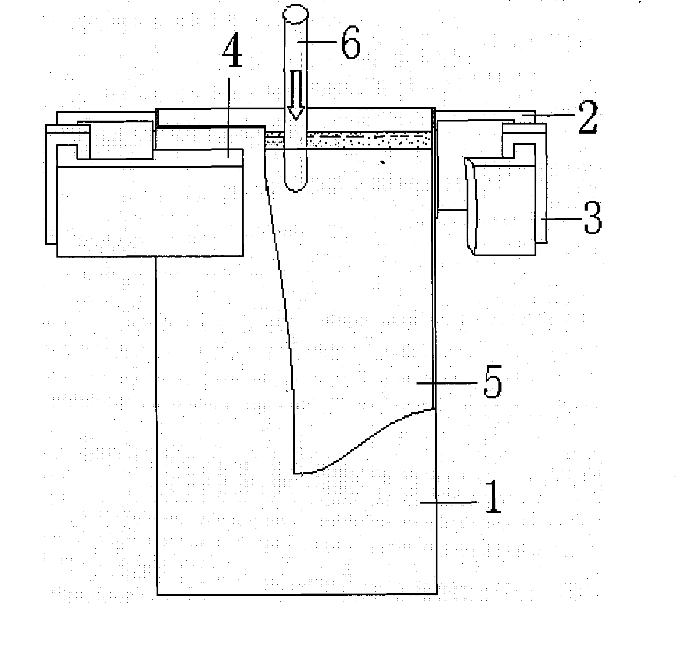
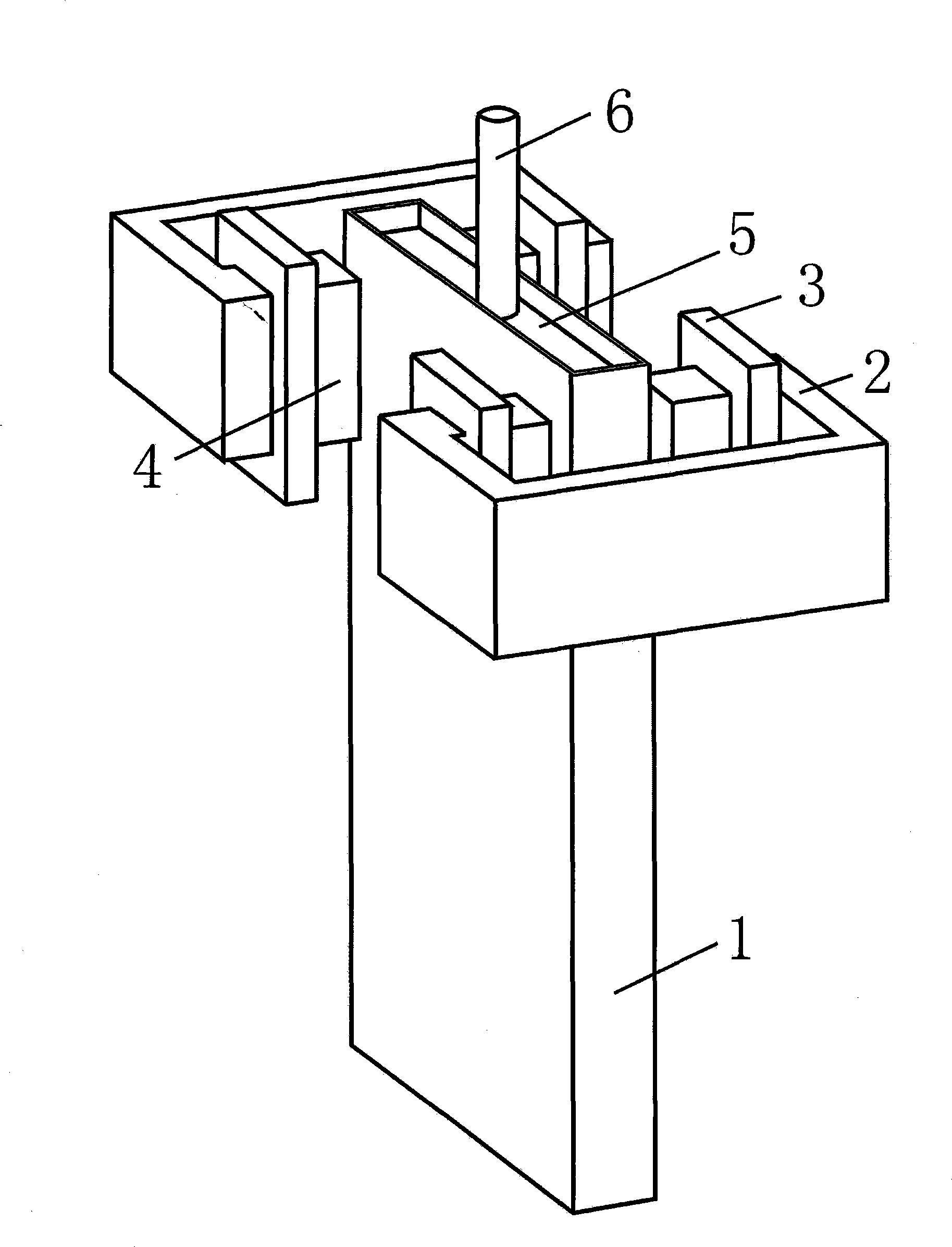
[0017] Such as figure 1 As shown, the electromagnetic braking device of the present invention is composed of a magnetic core 2 half-surrounded on the side wall of the crystallizer 1, an exciting coil 3 and a magnetic pole 4. The magnetic pole 4 is arranged on the narrow surface area biased to the mold 1, and the magnetic pole 4 is in height Simultaneously cover the surface area of ​​the molten metal 5 near the narrow face of the crystallizer 1 and the impact point area where the nozzle 6 flows out. By applying current to the excitation coil 3, a static magnetic field is generated between the two pairs of magnetic poles 4. The two groups of excitation in this embodiment The coils 3 are respectively arranged at the center of the magnetic core 2, on one side of the narrow side of the crystallizer.

[0018] For a mold with a cross-sectional size of 1400×230mm, a nozzle immersion depth of 150mm, and a nozzle side hole inclination angle of -15 degrees, the magnetic pole of the elect...

example 2

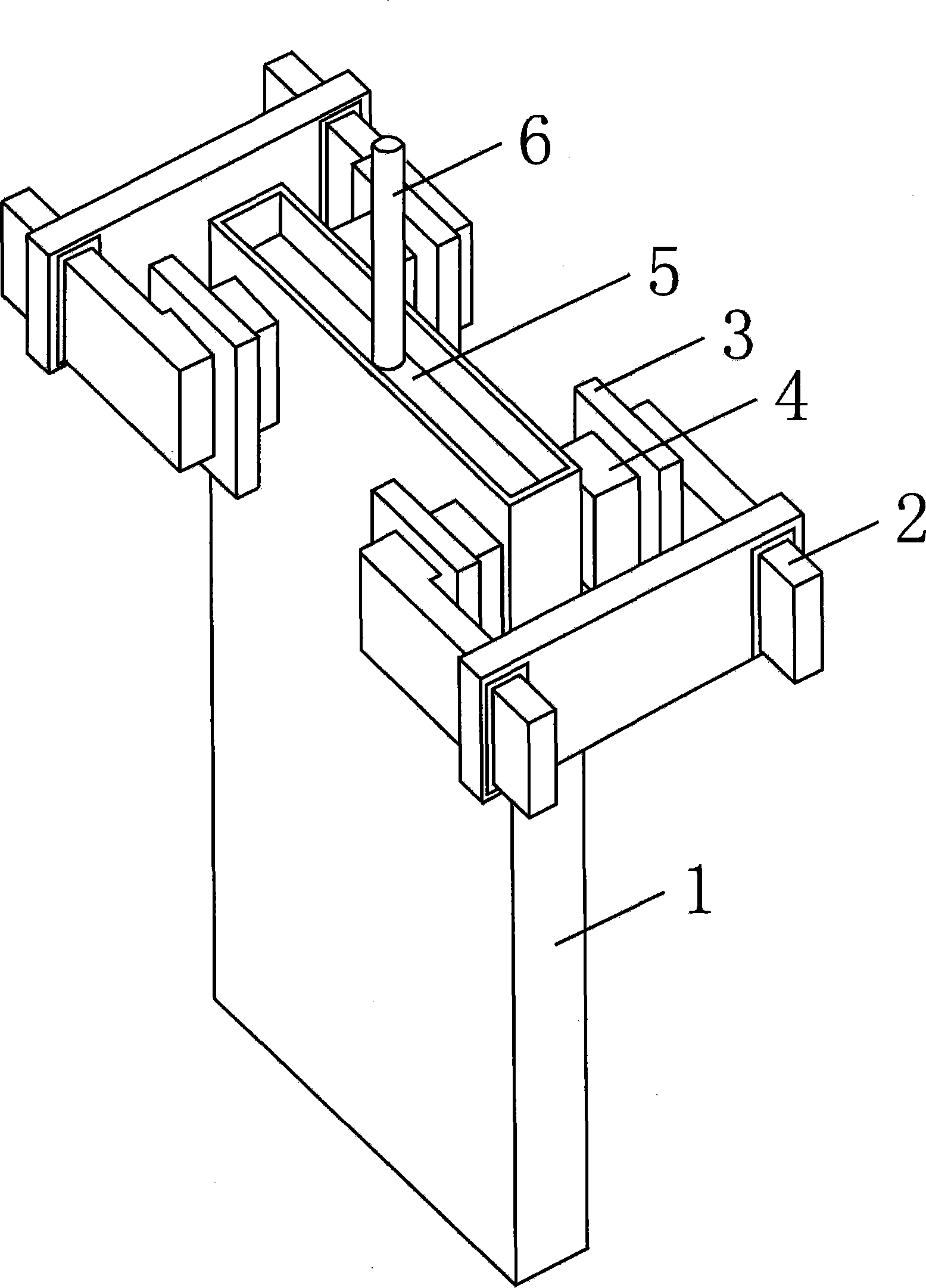
[0020] according to image 3 The arrangement scheme of magnetic poles, magnetic cores and excitation coils of the electromagnetic brake shown, and the connection method of magnetic poles and magnetic cores. For a mold with a cross-sectional size of 1400×230mm, a nozzle immersion depth of 150mm, and a nozzle side hole inclination angle of -15 degrees, the electromagnetic brake magnetic pole is placed near the narrow surface of the continuous casting mold. In the height direction, the top of the magnetic pole is located within the range from 50mm up to 500mm down from the molten steel surface of the mold; in the width direction, the magnetic pole is located within the range of 180mm inward from the side wall of the mold. That is, the cross-sectional size of the magnetic pole is 180×500mm, so that the magnetic pole simultaneously covers the surface area of ​​the molten metal near the narrow surface of the mold and the impact point area of ​​the outlet flow. When the width of the...

example 3

[0022] The structure of the device is the same as Example 1, the difference is that for a mold with a cross-sectional size of 1400×230mm, a nozzle immersion depth of 150mm, and a nozzle side hole inclination angle of -15 degrees, the magnetic pole of the electromagnetic brake is placed near the narrow surface of the continuous casting mold. In the height direction, the top of the magnetic pole is located within the range from 50mm up to 800mm down from the molten steel surface of the mold; in the width direction, the magnetic pole is located within the range of 400mm from the side wall of the mold. That is, the cross-sectional size of the magnetic pole is 400×800mm, so that the magnetic pole simultaneously covers the surface area of ​​the molten metal near the narrow surface of the mold and the impact point area of ​​the outlet flow. The magnetic core and the magnetic poles are integrally connected.


PUM

PropertyMeasurementUnit
magnetic flux densityaaaaaaaaaa

Abstract

The invention relates to an electromagnetic brake device for controlling the flow of metal liquid in a continuous casting crystallizer. The device is composed of a magnetic core which semi-surrounds the side wall of the crystallizer, an excitation coil and magnetic poles, the magnetic pole is arranged in a narrow-surface area which is inclined to the crystallizer, the magnetic pole simultaneouslycovers the surface area of the metal liquid which is in the vicinity of the narrow surface of the crystallizer and the area of an impact point of the outflow of a nozzle on the height, a static magnetic field is generated between two pairs of the magnetic poles by imposing the current on the excitation coil, the surface flow of the metal liquid which is in the vicinity of the narrow surface of the crystallizer and the flow of the area of the impact point of the outflow of the nozzle of the metal liquid in the crystallizer are simultaneously controller by the static magnetic field. The electromagnetic brake device has the advantages that: the electromagnetic brake device can simultaneously effectively inhibit the surface slag entrapment of the metal liquid which is in the vicinity of the narrow surface of the crystallizer and the impact depth of the metal liquid of the outflow of the nozzle, promote the upward floating and removal of inclusions, bubbles and other heterophase substancesof the front edge of a metal coagulation shell and weaken the influence degree of the immersion depth of the nozzle and the angle of the outflow of the nozzle on the electromagnetic brake effect during the changes; furthermore, the electromagnetic brake device has simple form and small structural size, the volume and weight ratios are greatly reduced compared with the volume and weight ratios of the electromagnetic brake device of the full-frame one-section and the full-frame two-section, thus saving energy and reducing consumption.

Description

technical field [0001] The invention belongs to the technical field of continuous casting, in particular to an electromagnetic braking device for controlling the flow of molten metal in a continuous casting crystallizer. Background technique [0002] In the usual continuous casting process of molten metal, the molten metal enters the mold through the nozzle, and the molten metal flowing out of the nozzle has a certain impact velocity, on the one hand, it causes the disturbance of the surface of the molten metal in the mold, and it is easy to displace the surface of the molten metal The slag liquid is brought into the molten metal to pollute the molten steel, especially in the area near the narrow surface of the mold. On the other hand, it causes an impact on the narrow surface of the crystallizer, which makes the metal solidification shell at this place thinner, and at the same time makes the inclusions, bubbles and other heterogeneous substances in the molten metal immerse ...

Claims


Application Information

Patent Timeline
Patent Type & Authority Patents(China)
IPC IPC(8): B22D11/115
Inventor 王恩刚赫冀成康丽陈芝会邓安元
Owner NORTHEASTERN UNIV LIAONING
Learn More