

Plane welding flange divided edge structure
A technology of plane welding and deforming structure, which is applied to the edge of the workpiece, metal processing equipment, manufacturing tools, etc., can solve the problems of insufficient weld penetration, poor spot welding firmness, and poor welding quality, and achieve good welding quality. The effect of firm spot welding and reduced amount of filler metal
- Summary
- Abstract
- Description
- Claims
- Application Information
AI Technical Summary
Problems solved by technology
Method used
Image

Examples
example 1
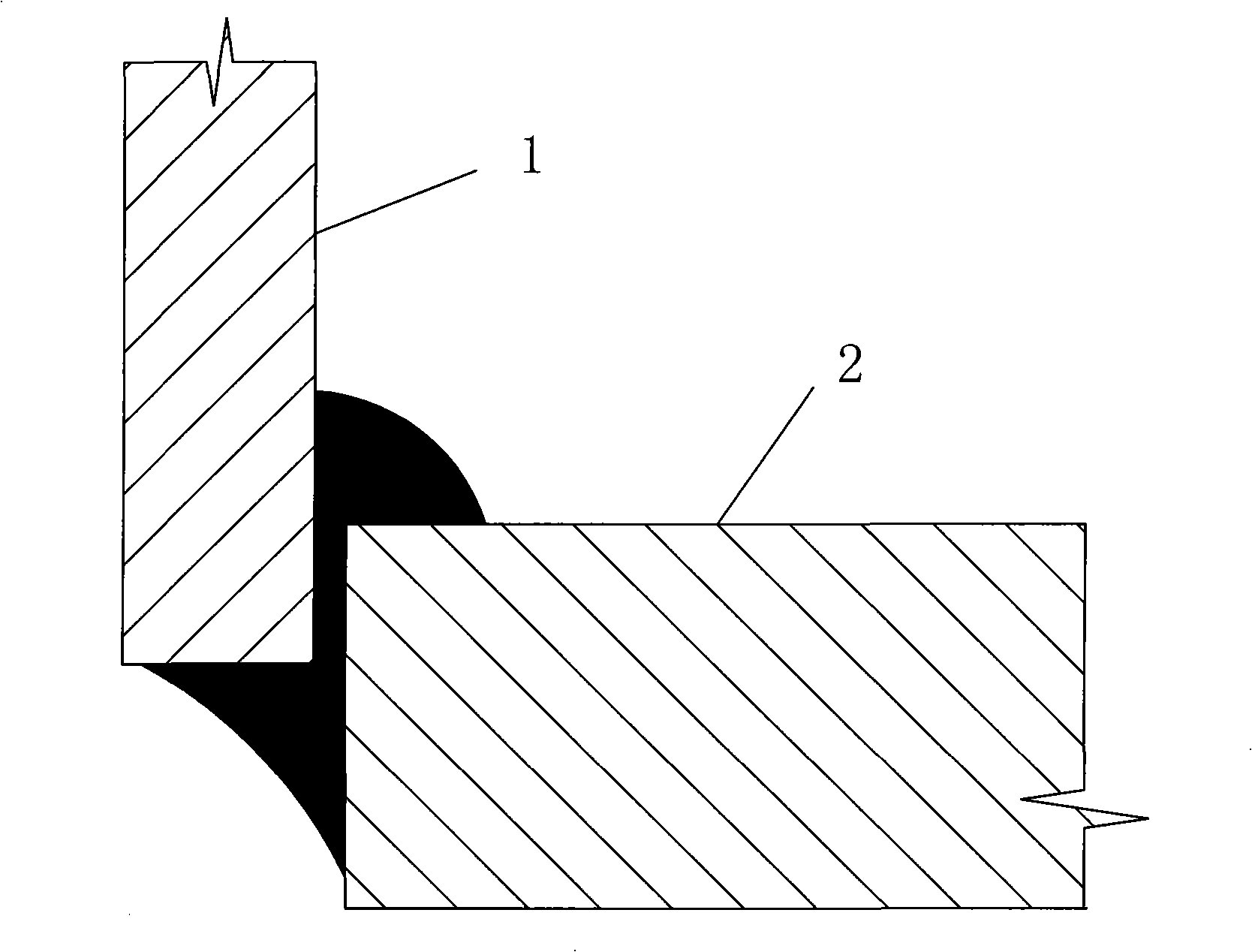
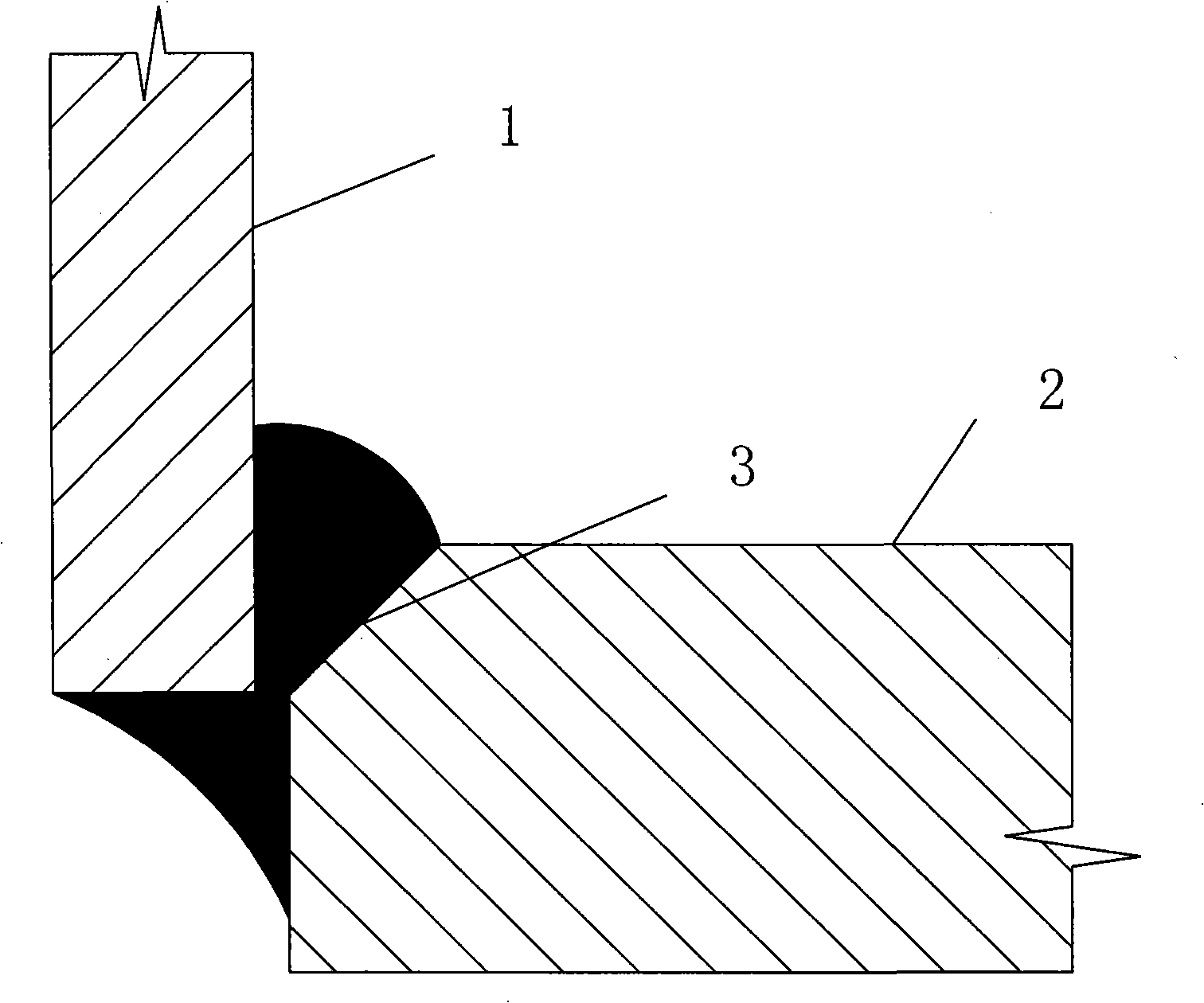
[0029] Example 1: The wall thickness of the steel pipe is 8cm, the thickness of the flange is 20cm, the distance between the end face of the inner ring of the flange and the side of the steel pipe is 2 to 3cm, and the angle between the circumferential groove and the steel pipe (vertical plane) is 45 degrees. The groove height of the circular groove is 6cm, the width of the circular groove is 5cm, the radius R of the inner chamfer of the circular groove is 3cm, the width of the blunt edge between the circular groove and the circular groove is 2cm, and the upper part of the weld The weld height relative to the upper surface of the flange is 2-3cm, the weld width of the upper part of the weld relative to the side of the steel pipe is 10-11cm, and the weld angle height of the lower part of the weld relative to the bottom surface of the steel pipe is 8cm.
example 2
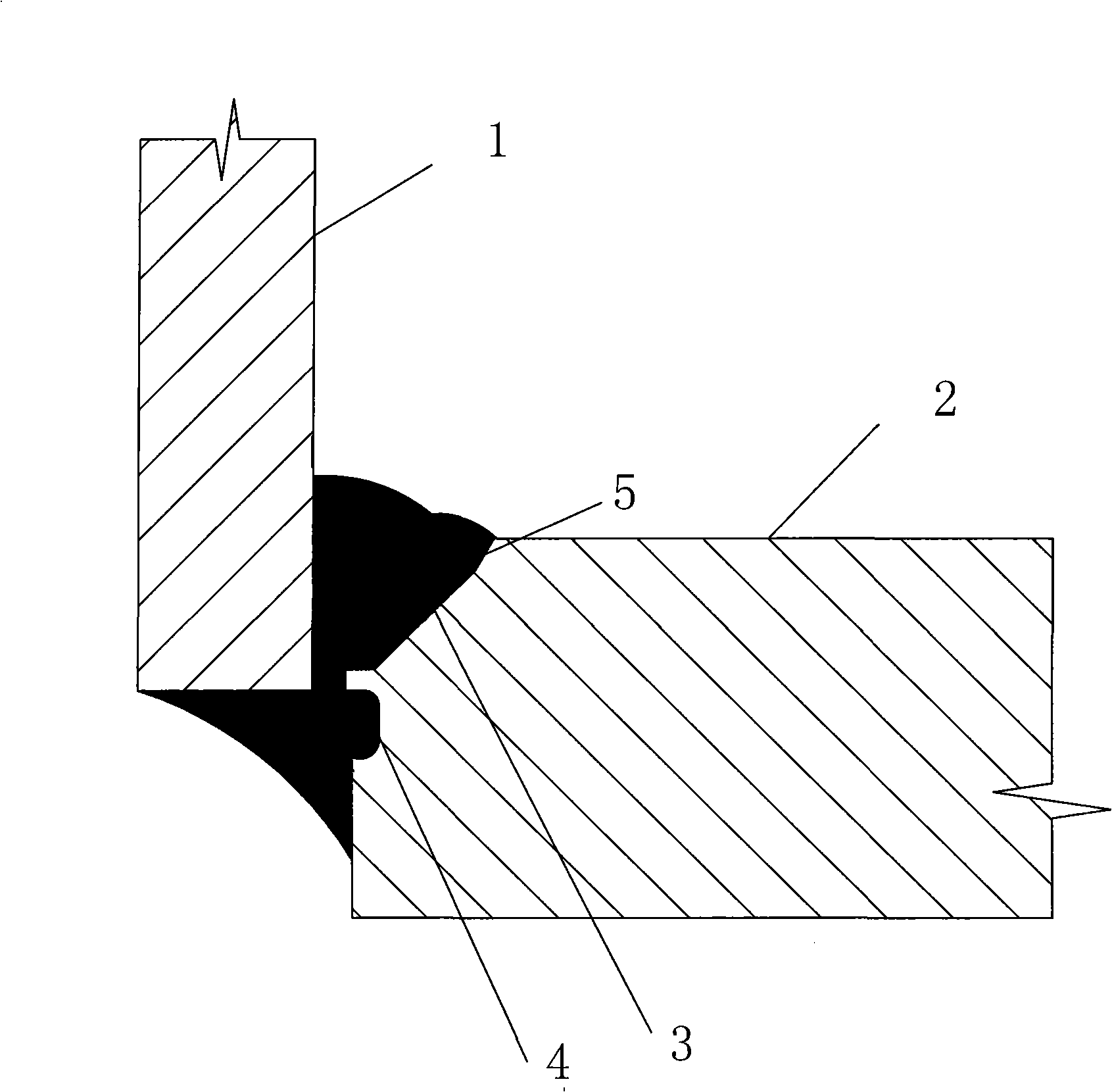
[0030] Example 2: The wall thickness of the steel pipe is 10cm, the thickness of the flange is 22cm, the distance between the end face of the inner ring of the flange and the side of the steel pipe is 2-3cm, and the angle between the circumferential groove and the steel pipe (vertical plane) is 55 degrees. The angle between the steep slope and the steel pipe (vertical plane) is 22.5 degrees, the groove height of the circumferential groove is 6cm, the height of the steep slope is 2cm, the width of the annular groove is 5cm, and the radius R of the inner chamfer of the annular groove is 3cm , the width of the blunt edge between the annular notch and the circumferential groove is 2cm, the weld height of the upper part of the weld relative to the upper surface of the flange is 3-4cm, and the weld width of the upper part of the weld relative to the side of the steel pipe 13-14cm, the height of the weld angle of the lower half of the weld relative to the bottom surface of the steel p...
example 3
[0031] Example 3: The wall thickness of the steel pipe is 12cm, the thickness of the flange is 30cm, the distance between the end face of the inner ring of the flange and the side of the steel pipe is 2 to 3cm, and the angle between the circumferential groove and the steel pipe (vertical plane) is 55 degrees. The angle between the steep slope and the steel pipe (vertical plane) is 22.5 degrees, the groove height of the circumferential groove is 6cm, the height of the steep slope is 4cm, the width of the annular groove is 5cm, and the radius R of the inner chamfer of the annular groove is 3cm , the width of the blunt edge between the annular groove and the circumferential groove is 2cm, the weld height of the upper part of the weld relative to the upper surface of the flange is 3-4cm, and the weld width of the upper part of the weld relative to the side of the steel pipe is 14cm ~15cm, the height of the weld angle of the lower half of the weld relative to the bottom surface of t...
PUM
| Property | Measurement | Unit |
|---|---|---|
| thickness | aaaaa | aaaaa |
| thickness | aaaaa | aaaaa |
| thickness | aaaaa | aaaaa |
Abstract
Description
Claims
Application Information