Optical plate, backlight module applying same and LCD device
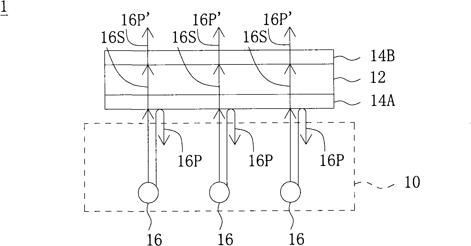
A liquid crystal display and backlight module technology, applied in optics, nonlinear optics, instruments, etc., can solve the problems of low light utilization rate of the backlight module 10 and the like
- Summary
- Abstract
- Description
- Claims
- Application Information
AI Technical Summary
Problems solved by technology
Method used
Image
Examples
no. 1 example
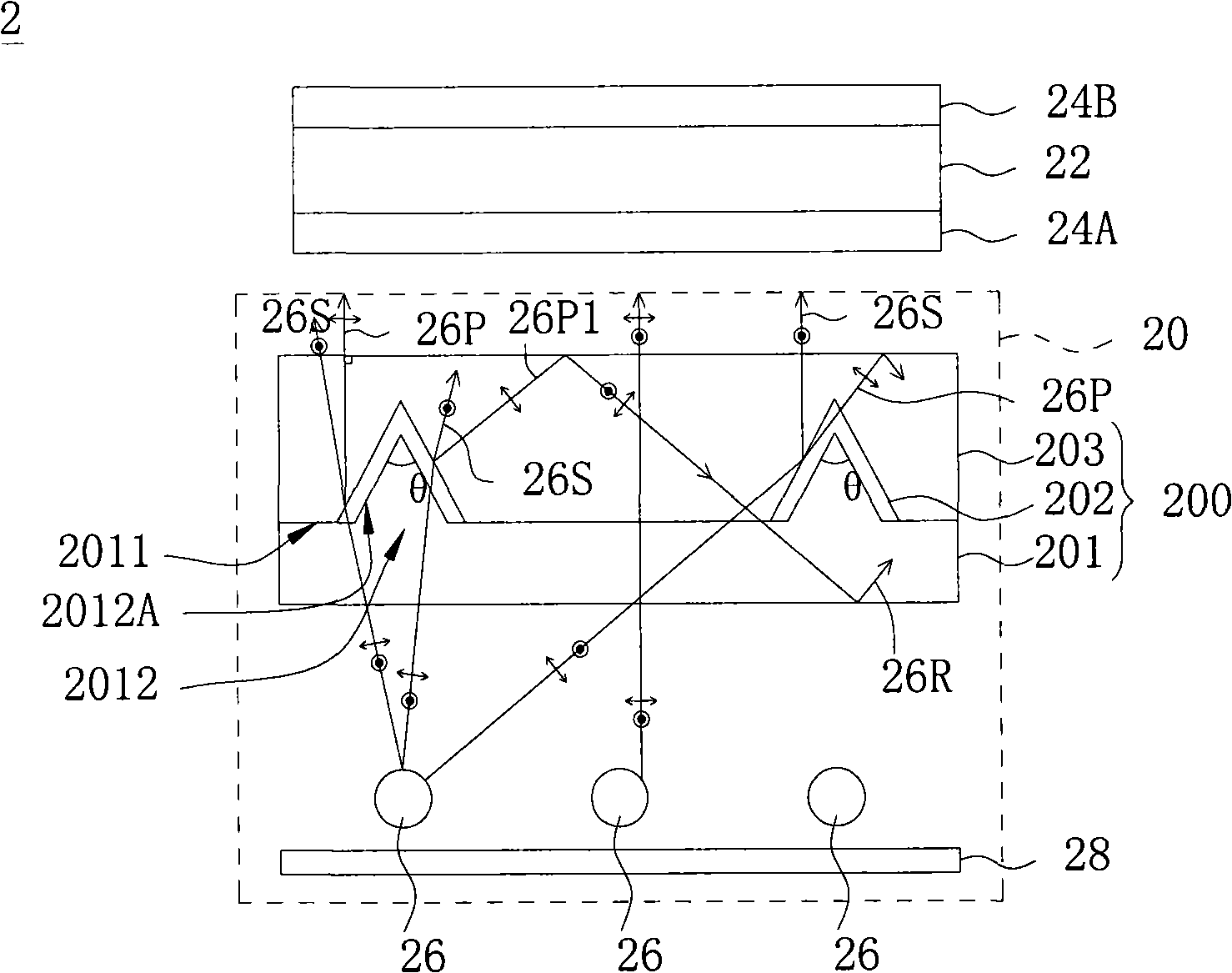
[0024] Please refer to figure 2 , figure 2 It is the liquid crystal display of the first embodiment of the present invention. The liquid crystal display 2 includes a liquid crystal display panel 22 , polarizers 24A, 24B attached to upper and lower surfaces of the liquid crystal display panel 22 , and a backlight module 20 . The components and descriptions of the liquid crystal display panel 22 and the polarizers 24A and 24B are as described in the prior art, and will not be repeated here.
[0025] The backlight module 20 includes an optical board 200 and a plurality of light sources 26. The backlight module 20 of this embodiment is an example of a direct type backlight module. Therefore, a plurality of light sources 26 are arranged under the optical board 200. The plurality of light sources 26 can be, for example, Cold-cathode fluorescent tubes, external electrode fluorescent tubes, mercury lamps, halogen lamps, or light-emitting diodes, etc., reflectors 28 are selectively...
no. 2 example
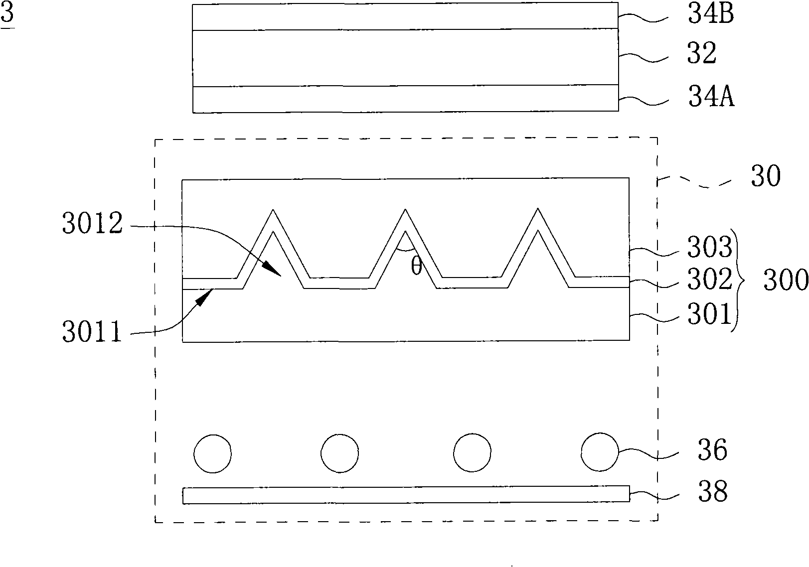
[0028] Please refer to image 3 , image 3 It is the liquid crystal display of the second embodiment of the present invention. The liquid crystal display 3 includes a liquid crystal display panel 32 , polarizers 34A, 34B attached to upper and lower surfaces of the liquid crystal display panel 32 , and a backlight module 30 . The components and descriptions of the liquid crystal display panel 32 and the polarizers 34A and 34B are as described in the prior art, and will not be repeated here.
[0029]The backlight module 30 includes an optical board 300 and a plurality of light sources 36. The backlight module 30 of this embodiment takes a direct-type backlight module as an example. Therefore, a plurality of light sources 36 are arranged under the optical board 300, and the plurality of light sources 36 are selectively placed under the optical board 300. A reflective plate 38 is arranged to reflect the light emitted downwards from the plurality of light sources 36 to improve li...
no. 3 example
[0031] Please refer to Figure 4 , Figure 4 It is the liquid crystal display of the third embodiment of the present invention. The liquid crystal display 4 includes a liquid crystal display panel 42 , polarizers 44A, 44B attached to upper and lower surfaces of the liquid crystal display panel 42 , and a backlight module 40 . The components and descriptions of the liquid crystal display panel 42 and the polarizers 44A and 44B are as described in the prior art, and will not be repeated here.
[0032] The backlight module 40 includes an optical plate 400 and a plurality of light sources 46. The backlight module 40 of this embodiment takes an edge-lit backlight module as an example. Therefore, the base 401 can be a light guide plate with a light guiding function, and the base 401 has a plurality of protrusions. portion 4012 and a plurality of flat portions 4011, wherein the convex portion 4012 and the flat portion 4011 are at least one-to-one staggered with each other, a plural...
PUM
| Property | Measurement | Unit |
|---|---|---|
| Thickness | aaaaa | aaaaa |
| Top angle | aaaaa | aaaaa |
| Spacing | aaaaa | aaaaa |
Abstract
Description
Claims
Application Information
 - R&D
- Intellectual Property
- Life Sciences
- Materials
- Tech Scout
- Unparalleled Data Quality
- Higher Quality Content
- 60% Fewer Hallucinations
Browse by: Latest US Patents, China's latest patents, Technical Efficacy Thesaurus, Application Domain, Technology Topic, Popular Technical Reports.
© 2025 PatSnap. All rights reserved.Legal|Privacy policy|Modern Slavery Act Transparency Statement|Sitemap|About US| Contact US: help@patsnap.com


