
Car top-set wireless device and its wireless amplifier

An antenna amplifier and receiving antenna technology, which is applied to antennas suitable for movable objects, radiating element structure forms, radiating element covers, etc. Beautiful design, increase the reception effect, improve the height effect

Active Publication Date: 2008-09-10
TAIZHOU SUZHONG ANTENNA GROUP
View PDF1 Cites 9 Cited by
  • Summary
  • Abstract
  • Description
  • Claims
  • Application Information

AI Technical Summary

Problems solved by technology

[0002] At present, the commonly used car antenna is a top-mounted rod antenna. Since the rod antenna is relatively long, installing it on the top of the car will affect the appearance of the whole car.
In addition, common antennas generally have the defect of being easy to break, the height of the antenna is too high, and it is not convenient to use when washing cars or entering places with limited space
In addition, during the use of the antenna, the antenna rod is easy to lose, and the antenna needs to be removed during transportation, which is inconvenient
Although there has been a shark fin antenna with a relatively low height and a beautiful appearance (such as Chinese patent application CN1841843A), due to the limited installation position of the antenna inside the housing, the car antenna is relatively close to the top of the car, and the radio signal is captured by the iron on the top of the car. plate absorption, which seriously affects the receiving effect of the antenna

Method used


Image

  • Car top-set wireless device and its wireless amplifier
  • Car top-set wireless device and its wireless amplifier
  • Car top-set wireless device and its wireless amplifier

Examples


Embodiment Construction

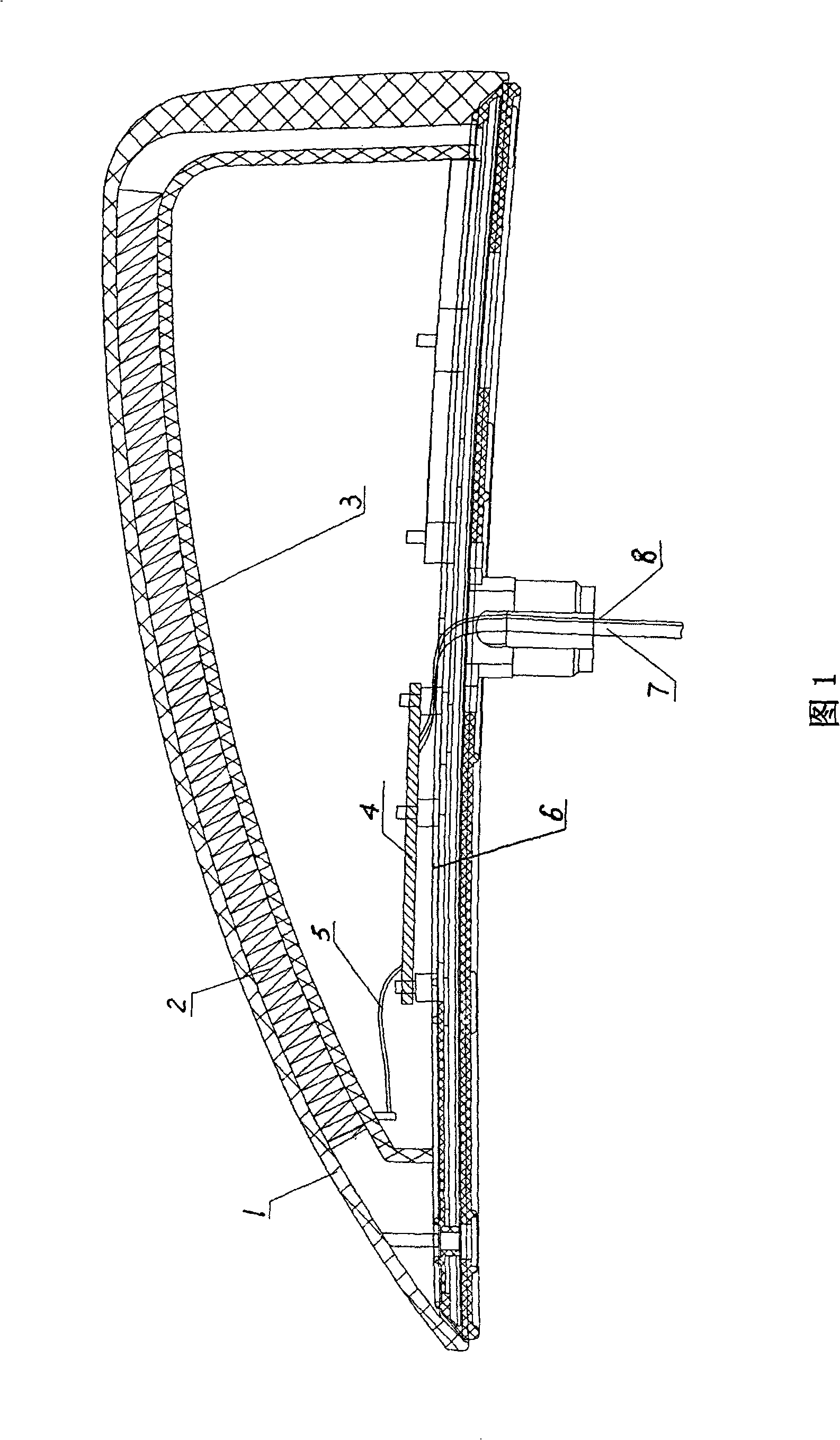
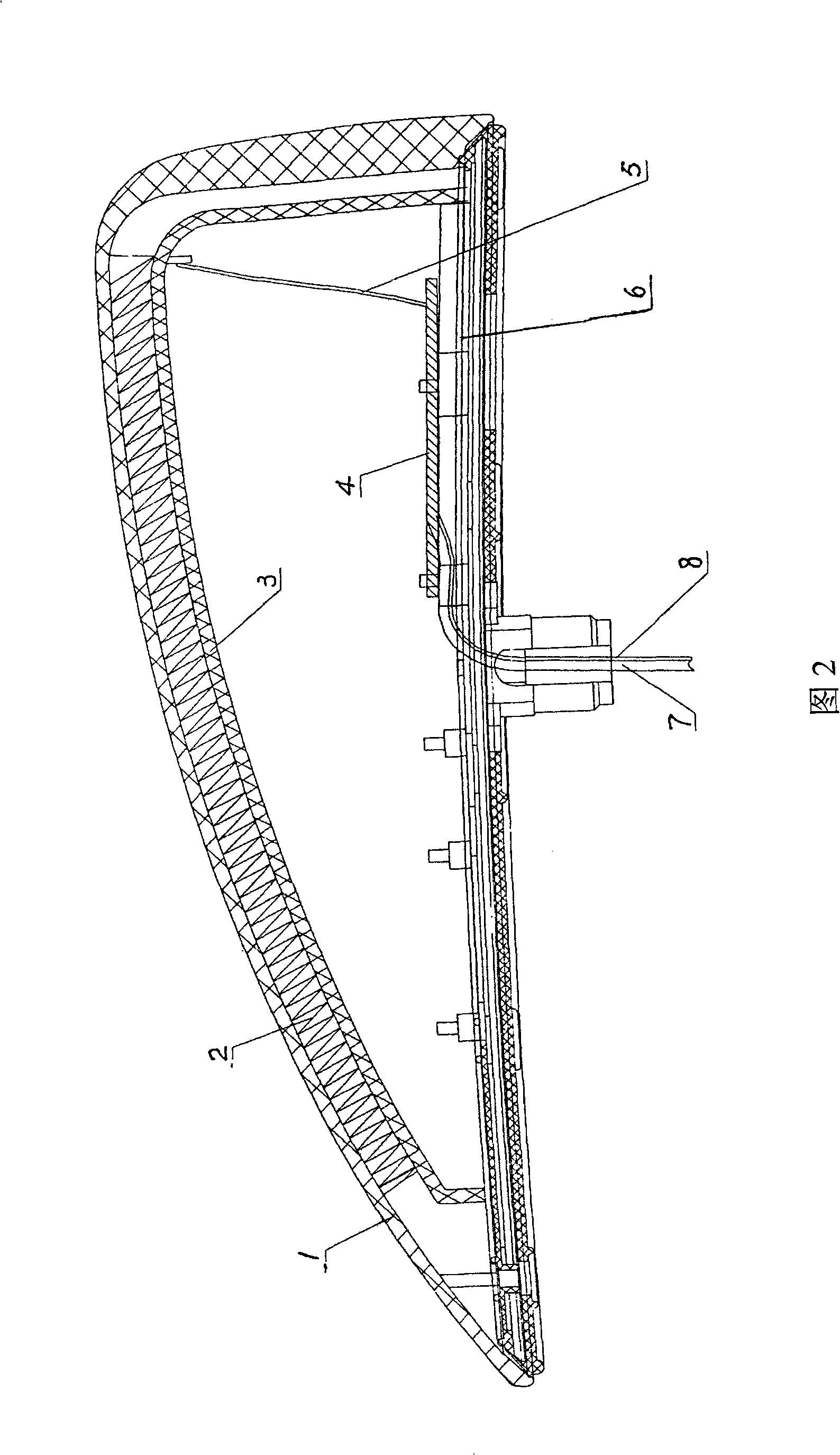
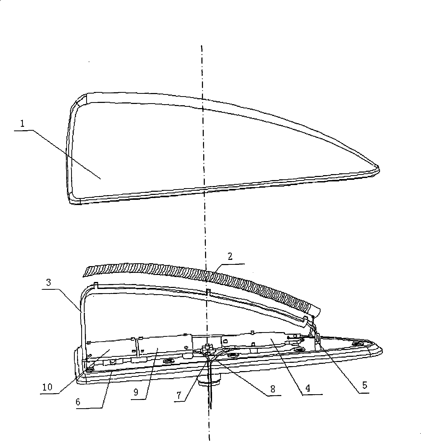
[0016] With reference to accompanying drawing 1~8, the antenna device of the present invention's automobile ceiling antenna device and antenna amplifier thereof has antenna housing 1, metal mounting base 6, antenna support 3 and radio receiving antenna 2, and antenna housing 1 is installed on the metal mounting base 6 , forming an internal accommodation space, which is provided with an antenna bracket 3, a radio receiving antenna 2 and a circuit board 4, the antenna bracket 3 and the circuit board 4 are installed on a metal mounting base 6, and the radio receiving antenna 2 is installed On the antenna bracket 3, or through injection molding or fixed card mounted on the upper part of the antenna shell inside; one end of the radio receiving antenna 2 is provided with an antenna signal output terminal, and the antenna signal output terminal passes through the wire 5 and the signal input terminal of the antenna amplifier of the circuit board Connection, the output signal of the ant...


PUM


Abstract

The invention relates to a vehicle overhead aerial system and an aerial amplifier thereof. The aerial amplifier comprises an AM frequency selection circuit, an AM signal amplifying circuit, an FM frequency selection circuit, an FM signal amplifying circuit and a power supply circuit, wherein, the aerial amplifier is further provided with a trapping circuit, one end of the trapping circuit is connected with the ground terminal of the aerial amplifier, and the other end thereof is connected with a metal aerial mounting base at the top of the vehicle. The aerial system is provided with a shark fin type aerial shell, a metal mounting base, an aerial frame and a wireless reception aerial; the aerial shell is arranged at the metal mounting base, which forms an internal accommodation space; the accommodation space is internally provided with the aerial frame, the wireless reception aerial and a circuit board which is provided with the aerial amplifier. The vehicle overhead aerial system and an aerial amplifier thereof increase the ground electric potential of the aerial amplifier at a printed circuit board, which is equal to increasing the height of the aerial amplifier to the metal mounting base, thus reducing the high frequency signals absorbed by the vehicle top, and increasing the receiving effect of the amplifier.

Description

technical field [0001] The present invention relates to an antenna device, especially a car roof antenna device and its antenna amplifier. The antenna device is a radio signal receiving antenna for a car, and its antenna amplifier is especially suitable for radio broadcasting AM / FM (Amplitude Modulation / Frequency Modulation) is used as a receiving device. Background technique [0002] At present, the commonly used car antenna is a top-mounted rod antenna. Since the rod antenna is relatively long, installing it on the top of the car will affect the appearance of the whole car. In addition, common antennas generally have the defect of being easily damaged. The height of the antenna is too high, and it is not convenient to use when washing cars or entering places with limited space. In addition, during the use of the antenna, the antenna rod is easy to lose, and the antenna needs to be removed during transportation, which is inconvenient. Although there has been a shark fin ...

Claims


Application Information

Patent Timeline
Patent Type & Authority Applications(China)
IPC IPC(8): H04B1/16H04B1/18H01Q1/32H01Q1/36H01Q1/42
Inventor 蒋小平
Owner TAIZHOU SUZHONG ANTENNA GROUP
Learn More