At present, most of the maintenance methods adopt manual inspection and regular OTDR to measure the
backup fiber. The maintenance effect of the optical cable is not ideal, and it is difficult to find the hidden dangers on the optical cable in a timely manner. When an obstacle occurs, it takes a long time to determine Whether it is a
transmission equipment failure or a cable failure, this maintenance method can no longer meet the needs of the ever-expanding maintenance scale of transmission optical cables. The daily maintenance of optical cables cannot only adopt the passive management method of "remedial work", and it is necessary to prevent the deterioration of optical fibers. Trends and eliminate hidden dangers in time
With the
rapid expansion of the basic network of optical cables in the province, the interruption of optical cables has also increased year by year. In order to ensure communication, it is required to invest more maintenance forces, strengthen maintenance methods, and improve maintenance levels. However, the current optical cable
maintenance system mainly It is difficult to meet higher-level maintenance requirements through decentralized and passive manual maintenance methods. The following are the outstanding problems faced in practice:
On the other hand, due to the short construction time of China Mobile's optical cable, there is an essential difference in line maintenance from China Telecom, and a large number of agent maintenance methods are used. Due to the consideration of maintenance costs, it is impossible to achieve the same level as China Telecom. , Complete line departments at all levels from the city to the county, but adopt the method of centralized setting of maintenance units. In a city, there are often only 1-2 maintenance centers (stations), and when a line failure occurs, the maintenance center (
Station) rushing to the fault point, it often takes a lot of
travel time, which virtually prolongs the fault duration
Secondly, since most of the current computer rooms are unmanned aerial vehicles, when the
transmission system of the primary, secondary and
remote computer rooms needs to define line faults and equipment failures, there is often a problem of unmanned cooperation in the computer room, resulting in some faults being unable to be accurately judged and maintenance efficiency. Low; Third, with the further deepening of the reform of the centralized
maintenance system, the technical force of on-site maintenance personnel is relatively weak, and the proficiency in instrument operation cannot be guaranteed. fourthly, the current
maintenance system mainly judges faults through the maintenance agency, and due to the limitations of various factors, the transmission
resource management system cannot be fully shared with the maintenance agency, and the fault judgment mainly relies on paper
Data search cannot guarantee the
time limit and accuracy of fault location, and it is impossible to automatically dispatch faults; fifth, according to statistics, current line faults account for 30-40% of the entire network faults, and the original maintenance system There is no effective judgment basis for the assessment of the
route, which leads to great controversy over the results of the
route assessment
[0005] Second, it is difficult to effectively maintain the optical cable actively
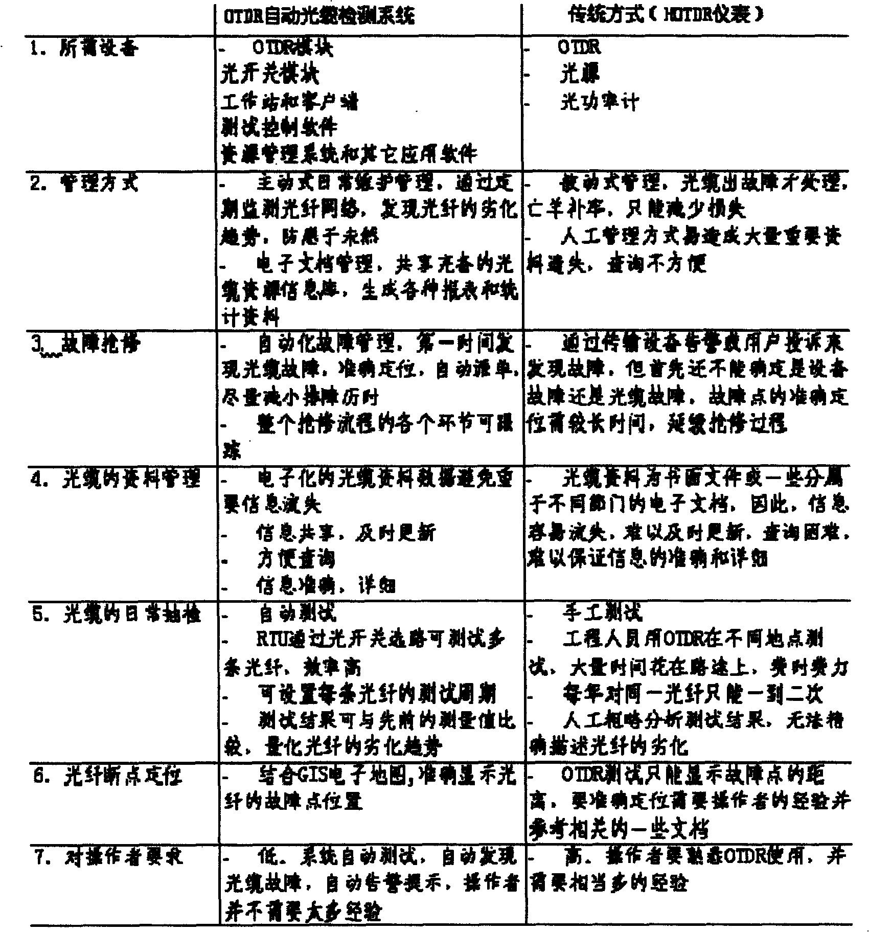
At present, under our agent maintenance system, manual inspection and regular use of OTDR to measure the
backup fiber are mostly used for maintenance. The effect of optical cable maintenance is not ideal, and it is difficult to find hidden dangers on the optical cable in a timely manner.
[0007] Manual inspection can only roughly judge the fault based on the obvious changes in the physical environment on the optical cable
route, and cannot detect the damage inside the optical cable in detail. The reasons for the unsatisfactory effect of regularly using OTDR to check the backup fiber are:
[0008] 1. The cost is high, and it takes a lot of labor and
material resources (OTDR instruments, vehicles) to be scattered to various locations, so the number of tests is quite limited, and only one or two sampling tests per year are required, making it difficult to find problems in time;
[0009] 2. The operator needs more OTDR experience and understands the actual situation of the optical cable under test;
[0010] 3. There is a lack of reference materials, and it is impossible to compare the deterioration trend of each key event point on the optical cable, and some fault events may be missed;
[0011] 4. Lack of management in maintaining
data records and updates;
[0012] 5. It is impossible to analyze the long-term trend of optical cable performance change
[0013] 3. The positioning of optical cable faults is slow and the
repair time is long
[0015] 1. It takes a long time to determine whether the SDH equipment is faulty or the cable is faulty;
[0016] 2. There is a lack of effective cooperation between departments. It will take a lot of manpower and time for mobile company personnel to go to the site to cooperate with the maintenance agency; it takes at least 45 minutes from the time when the monitoring personnel discover the fault to the notification of the maintenance agency to arrive at the scene, and to locate the fault. could take an hour;
[0017] 3. Lack of means to quickly and accurately locate the
exact location of the fault point
With the further enrichment of centralized construction methods, the comprehensive
network management of the
transmission network, the transmission
resource management system, the line inspection system, and the
SMS gateway have gradually become popular. The current optical cable maintenance methods cannot realize the joint application between systems to ensure the entire network Centralized monitoring and centralized maintenance
[0018] 4. How to effectively use and assess maintenance agents when maintenance tasks are heavy and corresponding personnel are lacking
However, in the current situation, when the optical cable fails, the personnel of the mobile company still need to cooperate on site, which does not really reduce the
workload of mobile engineers, and there is also a lack of objective and accurate
assessment methods for the maintenance quality
