Rear wheel suspension for a motorcycle and swing arm attachment structure for a motorcycle

A technology for motorcycles and rear wheels, which is applied to bicycle accessories, axle suspension devices, transportation and packaging, etc., to achieve the effect of lowering the vehicle's center of gravity and improving driving performance

Inactive Publication Date: 2008-09-24
HONDA MOTOR CO LTD
View PDF3 Cites 2 Cited by
  • Summary
  • Abstract
  • Description
  • Claims
  • Application Information

AI Technical Summary

Problems solved by technology

[0009] The present invention was made to solve the problems related to Japanese Patent Publication Hei 1-34830 and Japanese Patent Laid-Open No. 2004-352209

Method used


Image

  • Rear wheel suspension for a motorcycle and swing arm attachment structure for a motorcycle
  • Rear wheel suspension for a motorcycle and swing arm attachment structure for a motorcycle
  • Rear wheel suspension for a motorcycle and swing arm attachment structure for a motorcycle

Examples


no. 1 approach

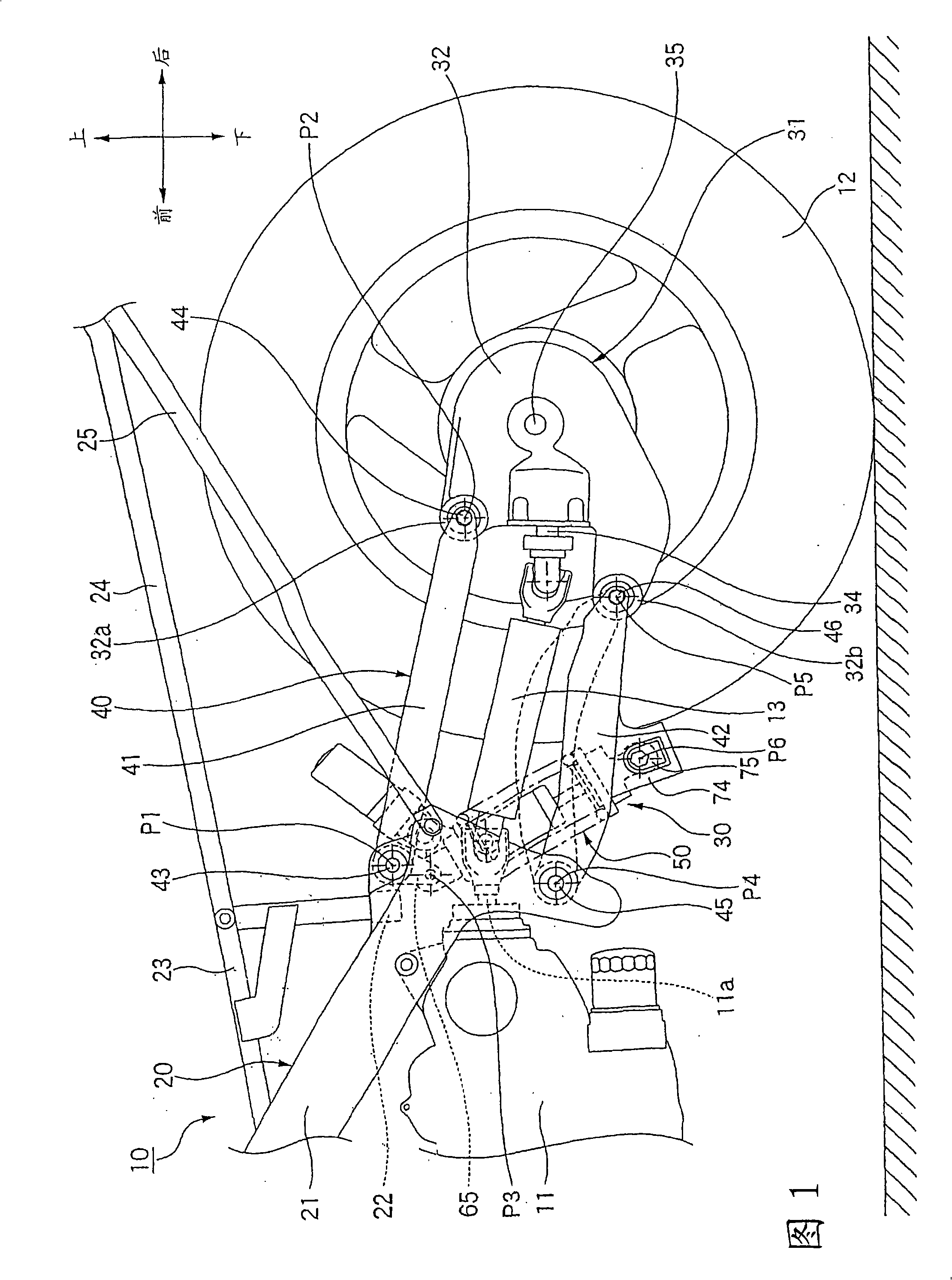
[0042] A motorcycle 10 according to a first embodiment of the present invention will be described with reference to FIG. 1 . The motorcycle 10 includes a body frame 20 . The power unit 11 is attached to the vehicle body frame 20 from below, and includes an internal combustion engine and a transmission. The rear wheel suspension 30 is swingably supported by the lower portion of the vehicle body frame 20 . The rear wheel 12 is rotatably supported by a rear end of a rear wheel suspension 30 .

[0043] The vehicle body frame 20 includes a pair of main frames 21 , cross members 22 , sub frames 23 , seat frames 24 and side frames 25 . The main frame 21 extends rearwardly and downwardly from a not-shown head pipe. The cross member 22 connects the middle portion of the main frame 21 in the vehicle width direction. The sub frame 23 is joined to the upper portion of the main frame 21 and to the upper surface of the cross member 22 . The seat frame 24 is joined to the sub frame 23 a...

no. 2 approach

[0067] A motorcycle 10 according to a second embodiment of the present invention will be described with reference to FIG. 7 . The motorcycle 10 includes a body frame 20 . The power unit 11 is attached to the vehicle body frame 20 from below, and includes an internal combustion engine and a transmission. The rear wheel suspension 30 is swingably supported by the lower portion of the vehicle body frame 20 . The rear wheel 12 is rotatably supported by a rear end of a rear wheel suspension 30 .

[0068] The vehicle body frame 20 includes a pair of main frames 21 , cross members 22 , sub frames 23 , seat frames 24 and side frames 25 . The main frame 21 extends rearwardly and downwardly from a not-shown head pipe. The cross member 22 connects the middle portion of the main frame 21 in the vehicle width direction. The sub frame 23 is joined to the upper portion of the main frame 21 and to the upper surface of the cross member 22 . The seat frame 24 is joined to the sub frame 23 ...


PUM


Abstract

A rear wheel suspension for a motorcycle can sufficiently ensure the stroke of a rear cushion and can enhance traveling performance of a vehicle by lowering the gravity center of the vehicle. A swing arm includes an upper arm swingably connecting a body frame with the upper portion of a power transmission portion. A lower arm swingably connects the body frame with the lower portion of the power transmission portion. The axial center of the upper end support portion of a rear cushion is swingably supported by the upper arm at a position forward of the axial center of the support portion. The axial center of the lower support portion of the rear cushion can swingably be supported by the lower arm at a position rearward of the axial center of the support portion swingably supporting the lower arm and the body frame with respect to the vehicle.

Description

technical field [0001] The present invention relates generally to rear wheel suspensions for motorcycles, and more particularly to such a rear wheel suspension for motorcycles comprising a swing arm rotatably supporting the rear wheel and a Rear bumper. [0002] The present invention also relates generally to a swing arm attachment structure for a motorcycle, and more particularly to an attachment structure for a swing arm having a parallel linkage arrangement of a pair of upper and lower arms. Background technique [0003] There are known rear wheel suspensions for motorcycles in which a rear shock absorber is arranged on an upper portion of a vehicle body to extend in the front-rear direction of the vehicle body (for example, see Japanese Patent Publication Hei 1-34830); and a rear shock absorber arrangement to extend in the vertical direction of the vehicle body (for example, refer to Japanese Patent Laid-Open No. 2004-352209). [0004] In the rear wheel suspension for ...

Claims


Application Information

Patent Timeline
Patent Type & Authority Applications(China)
IPC IPC(8): B62K25/26
Inventor 五十岚真高柳真二高村俊明津田刚早川公视
Owner HONDA MOTOR CO LTD
Why Eureka
Try Eureka